

Question: I ONLY NEED GATE LEVEL CIRCUIT. PREFERABLY LOGISIM 1 The Objective The principle objective of this part is to have you review your skills with
I ONLY NEED GATE LEVEL CIRCUIT. PREFERABLY LOGISIM
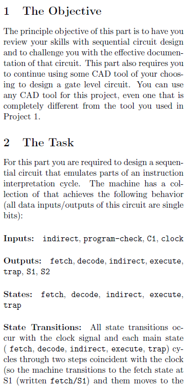
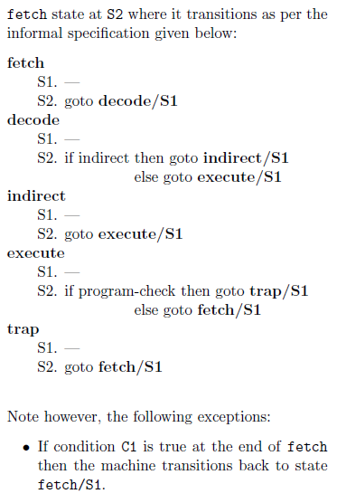
1 The Objective The principle objective of this part is to have you review your skills with sequential circuit design and to challenge you with the effective documen- tation of that circuit. This part also requires you to continue using some CAD tool of your choos- ing to design a gate level circuit. You can use any CAD tool for this project, even one that is completely different from the tool you used in Project 1. 2 The Task For this part you are required to design a sequen- tial circuit that emulates parts of an instruction interpretation cycle. The machine has a col- lection of that achieves the following behavior (all data inputs/outputs of this circuit are single bits): Inputs: indirect, program-check, C1, clock Outputs: fetch, decode, indirect, execute, trap, S1, S2 States: fetch, decode, indirect, execute, trap State Transitions: All state transitions oc- cur with the clock signal and each main state ( fetch, decode, indirect, execute, trap) cy- cles through two steps coincident with the clock (so the machine transitions to the fetch state at si (written fetch/S1) and them moves to the fetch state at S2 where it transitions as per the informal specification given below: fetch S1. S2. goto decode/S1 decode S1. S2. if indirect then goto indirect/S1 else goto execute/S1 indirect S1. S2. goto execute/S1 execute S1. S2. if program-check then goto trap/S1 else goto fetch/S1 trap S1. S2. goto fetch/S1 Note however, the following exceptions: . If condition C1 is true at the end of fetch then the machine transitions back to state fetch/S1. 1 The Objective The principle objective of this part is to have you review your skills with sequential circuit design and to challenge you with the effective documen- tation of that circuit. This part also requires you to continue using some CAD tool of your choos- ing to design a gate level circuit. You can use any CAD tool for this project, even one that is completely different from the tool you used in Project 1. 2 The Task For this part you are required to design a sequen- tial circuit that emulates parts of an instruction interpretation cycle. The machine has a col- lection of that achieves the following behavior (all data inputs/outputs of this circuit are single bits): Inputs: indirect, program-check, C1, clock Outputs: fetch, decode, indirect, execute, trap, S1, S2 States: fetch, decode, indirect, execute, trap State Transitions: All state transitions oc- cur with the clock signal and each main state ( fetch, decode, indirect, execute, trap) cy- cles through two steps coincident with the clock (so the machine transitions to the fetch state at si (written fetch/S1) and them moves to the fetch state at S2 where it transitions as per the informal specification given below: fetch S1. S2. goto decode/S1 decode S1. S2. if indirect then goto indirect/S1 else goto execute/S1 indirect S1. S2. goto execute/S1 execute S1. S2. if program-check then goto trap/S1 else goto fetch/S1 trap S1. S2. goto fetch/S1 Note however, the following exceptions: . If condition C1 is true at the end of fetch then the machine transitions back to state fetch/S1
Step by Step Solution
There are 3 Steps involved in it

Get step-by-step solutions from verified subject matter experts