

Question: I want the correct answer. Don't copy paste. Figure 4 shows a general plan of a ( 9 0 f t 2 5 0 f
I want the correct answer. Don't copy paste.
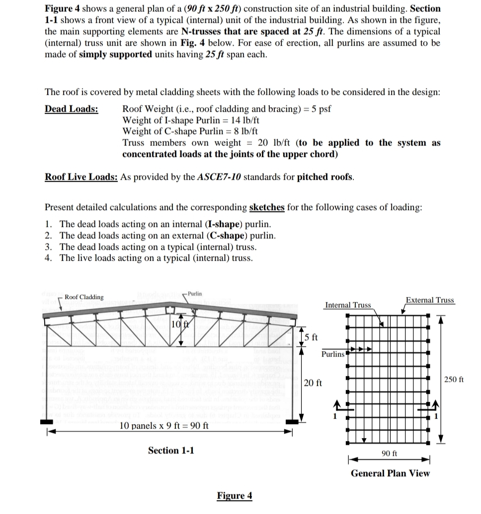
Figure shows a general plan of a construction site of an industrial building. Section shows a front view of a typical internal unit of the industrial building. As shown in the figure, the main supporting elements are trusses that are spaced at ft The dimensions of a typical internal truss unit are shown in Fig. below. For ease of erection, all purlins are assumed to be made of simply supported units having ft span each.
The roof is covered by metal cladding sheets with the following loads to be considered in the design:
Dead Loads: Roof Weight ie roof cladding and bracing
Weight of Ishape Purlin
Weight of Cshape Purlin
Truss members own weight to be applied to the system as concentrated loads at the joints of the upper chord
Roof Live Loads: As provided by the ASCE standards for pitched roofs.
Present detailed calculations and the corresponding sketches for the following cases of loading:
The dead loads acting on an internal Ishape purlin.
The dead loads acting on an external Cshape purlin.
The dead loads acting on a typical internal truss.
The live loads acting on a typical internal truss.
Figure
Step by Step Solution
There are 3 Steps involved in it
1 Expert Approved Answer
Step: 1 Unlock

Question Has Been Solved by an Expert!
Get step-by-step solutions from verified subject matter experts
Step: 2 Unlock
Step: 3 Unlock