

Question: id is 20180151 ... please do not post wrong answer .. Digital Logic Design Mini-Project Description In this mini-project, you are required to design a
 id is 20180151 ... please do not post wrong answer ..
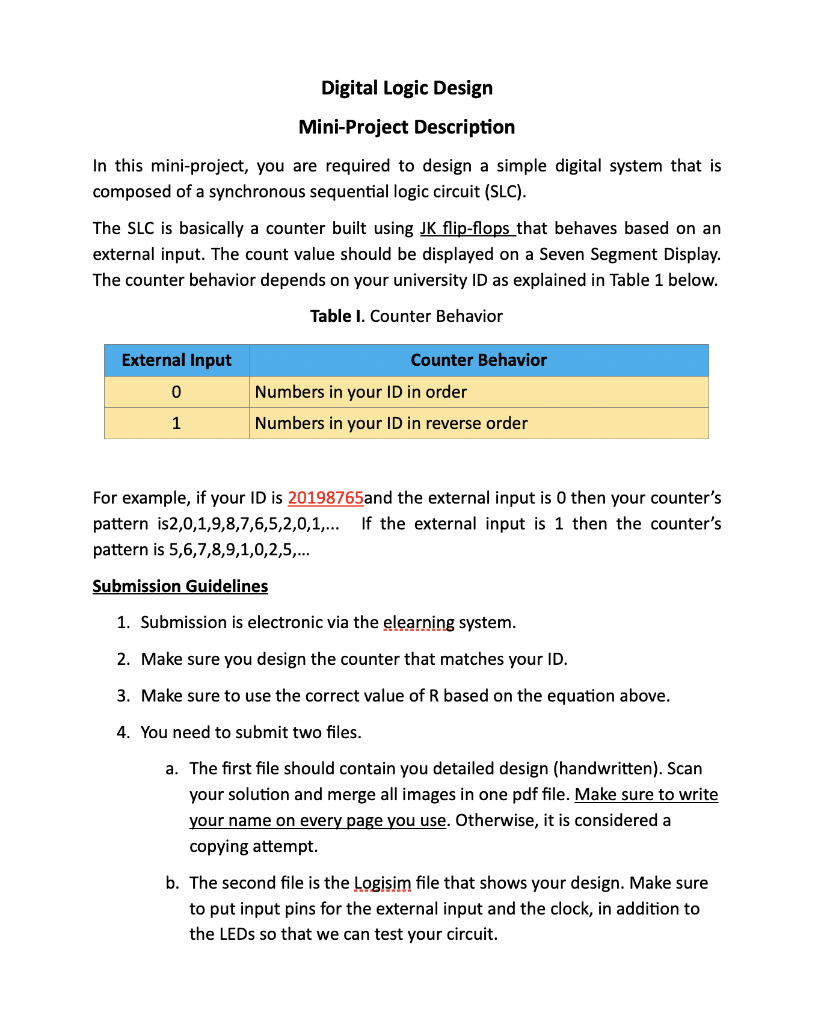
Digital Logic Design Mini-Project Description In this mini-project, you are required to design a simple digital system that is composed of a synchronous sequential logic circuit (SLC). The SLC is basically a counter built using JK flip-flops that behaves based on an external input. The count value should be displayed on a Seven Segment Display. The counter behavior depends on your university ID as explained in Table 1 below. Table I. Counter Behavior External Input Counter Behavior 0 Numbers in your ID in order Numbers in your ID in reverse order 1 For example, if your ID is 20198765and the external input is 0 then your counter's pattern is2,0,1,9,8,7,6,5,2,0,1,... If the external input is 1 then the counter's pattern is 5,6,7,8,9,1,0,2,5,... Submission Guidelines 1. Submission is electronic via the elearning system. 2. Make sure you design the counter that matches your ID. 3. Make sure to use the correct value of R based on the equation above. 4. You need to submit two files. a. The first file should contain you detailed design (handwritten). Scan your solution and merge all images in one pdf file. Make sure to write your name on every page you use. Otherwise, it is considered a copying attempt. b. The second file is the Logisim file that shows your design. Make sure to put input pins for the external input and the clock, in addition to the LEDs so that we can test your circuit. Digital Logic Design Mini-Project Description In this mini-project, you are required to design a simple digital system that is composed of a synchronous sequential logic circuit (SLC). The SLC is basically a counter built using JK flip-flops that behaves based on an external input. The count value should be displayed on a Seven Segment Display. The counter behavior depends on your university ID as explained in Table 1 below. Table I. Counter Behavior External Input Counter Behavior 0 Numbers in your ID in order Numbers in your ID in reverse order 1 For example, if your ID is 20198765and the external input is 0 then your counter's pattern is2,0,1,9,8,7,6,5,2,0,1,... If the external input is 1 then the counter's pattern is 5,6,7,8,9,1,0,2,5,... Submission Guidelines 1. Submission is electronic via the elearning system. 2. Make sure you design the counter that matches your ID. 3. Make sure to use the correct value of R based on the equation above. 4. You need to submit two files. a. The first file should contain you detailed design (handwritten). Scan your solution and merge all images in one pdf file. Make sure to write your name on every page you use. Otherwise, it is considered a copying attempt. b. The second file is the Logisim file that shows your design. Make sure to put input pins for the external input and the clock, in addition to the LEDs so that we can test your circuit
Step by Step Solution
There are 3 Steps involved in it

Get step-by-step solutions from verified subject matter experts