

Question: IIme Remaining Problem set 1 Red lines are axes. There is a frictionless pin joint at point that ic free to rotate about the y
IIme Remaining
Problem set
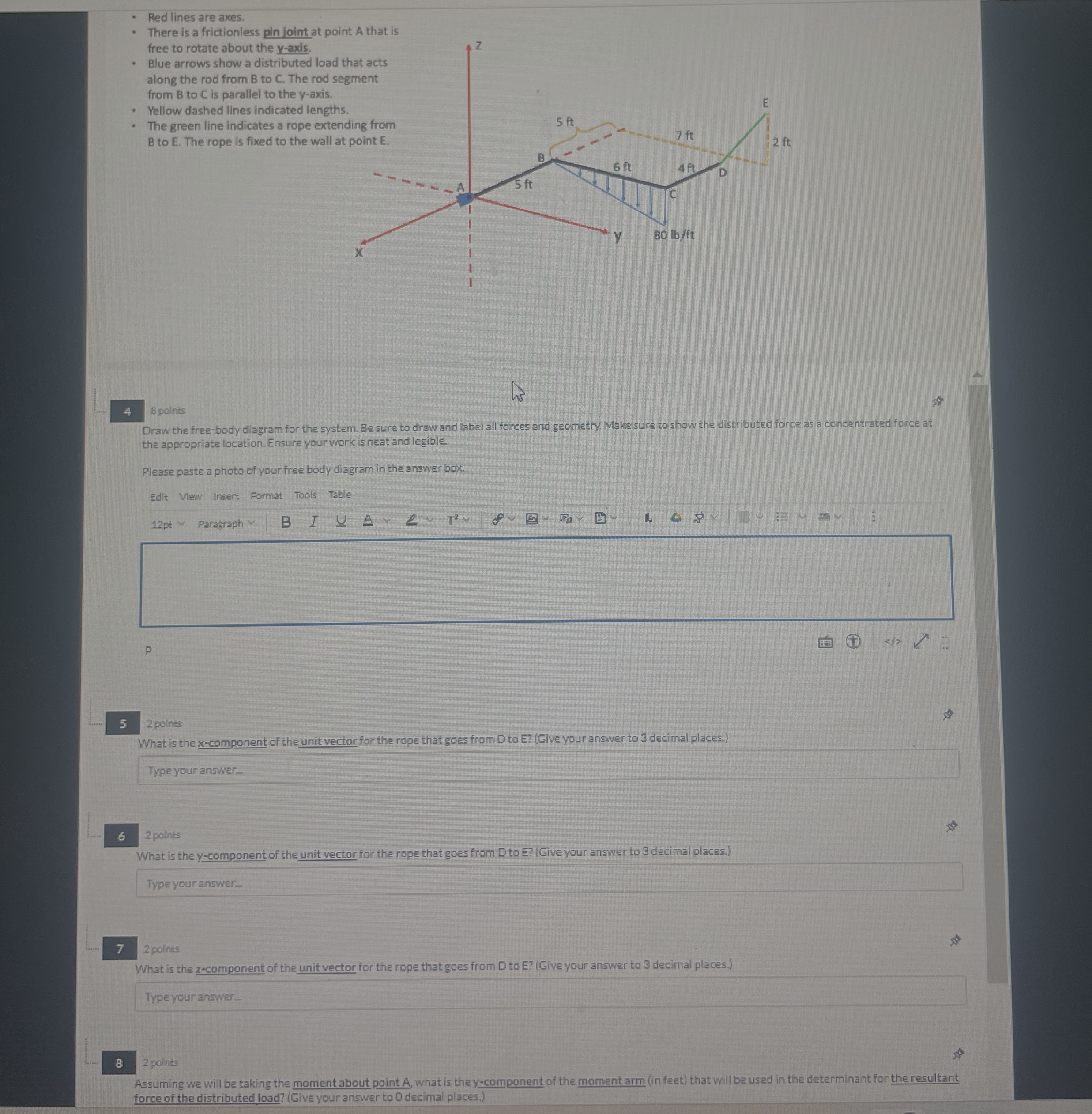
Red lines are axes.
There is a frictionless pin joint at point that ic free to rotate about the yaxis.
Blue arrows show a distributed load along the rod from to The rod from to is parallel to the axis.
Yellow dashed lines indicated length
The green line indicates a rope exter to The rope is fixed to the wall a
points
What is the xcomponent of the unit vector for the rope that goes from to Give your answer to decimal places.
Type your answer...
points
What is the ycomponent of the unit vector for the rope that goes from D to EGive your answer to decimal places.
Type your answer...
points
What is the zcomponent of the unit vector for the rope that goes from D to EGive your answer to decimal places.
Type your answer...
points
Assuming we will be taking the moment about point what is the component of the moment arm in feet that will be used in the determinant for the resultant force of the distributed load? Give your answer to decimal places.
Type your answer...
points
FOR ALL FOLLOWING QUESTIONS, assume the following force vectors and moment arms for the system:
Red lines are axes.
There is a frictionless pin joint at point A that is free to rotate about the axis.
Blue arrows show a distributed load tha along the rod from to The rod segn from to is parallel to the axis.
Yellow dashed lines indicated lengths.
The green line indicates a rope extendin to The rope is fixed to the wall at
points
Draw the freebody diagram for the system. Be sure to draw and label all forces and geometry. Make sure to show the distributed force as a concentrated force at the appropriate location. Ensure your work is neat and legible.
Please paste a photo of your free body diagram in the answer box.
Red lines are axes.
There is a frictionless pin joint at point A that is free to rotate about the axis.
Blue arrows show a distributed load that acts along the rod from to The rod segment from to is parallel to the axis.
Yellow dashed lines indicated lengths.
The green line indicates a rope extending from to The rope is fixed to the wall at point
points
Draw the freebody diagram for the system. Be sure to draw and label all forces and geometry. Make sure to show the distributed force as a concentrated force at the appropriate location. Ensure your work is neat and legible.
Please paste a photo of your free body diagram in the answer box.
Red lines are axes.
There is a frictionless pin joint at po free to rotate about the axis.
Blue arrows show a distributed loas along the rod from to The rods from to is parallel to the axis.
Yellow dashed lines indicated lengt
The green line indicates a rope exte B to E The rope is fixed to the wall
polints
Draw the freebody diagram for the system. Be sure to draw and label all fonces and geometry. Make sure to show the distributed force as a concentrated force at the appropriate location. Ensure your work is neat and legible.
Please paste a photo of your free body diagram in the answer box.
Edit Vlew Insert Format Tools Table
Type your answer
points
What is the ycomponent of the unit vector for the rope that goes from D to EGive your answer to decimal places.
Type your answer
points
What i the
Type
polints
Assuming we will be taking the moment about point what is the component of the moment arm in feet that will be used in the determinant for the resultant force of the distributed load? Give your answer to decimal places.
Step by Step Solution
There are 3 Steps involved in it
1 Expert Approved Answer
Step: 1 Unlock

Question Has Been Solved by an Expert!
Get step-by-step solutions from verified subject matter experts
Step: 2 Unlock
Step: 3 Unlock