

Question: Im working on corrections for structured computer organization. Can someone help me with corrections/solutions for the following questions. along with step by step explanations of
Im working on corrections for structured computer organization. Can someone help me with corrections/solutions for the following questions. along with step by step explanations of how they got the answer. please help
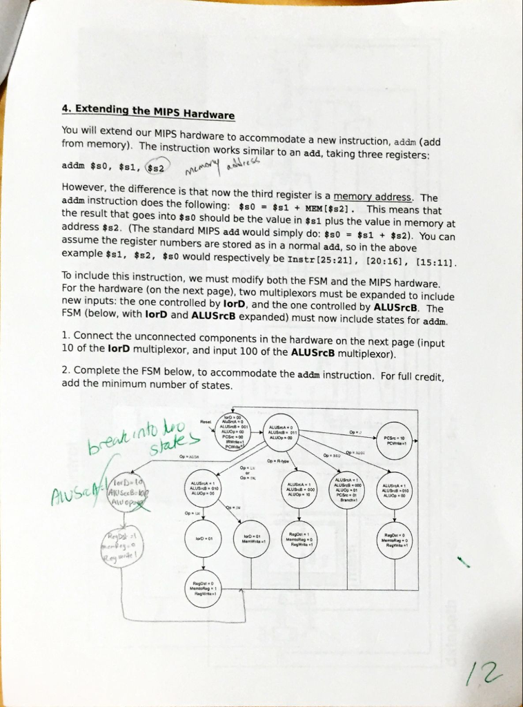
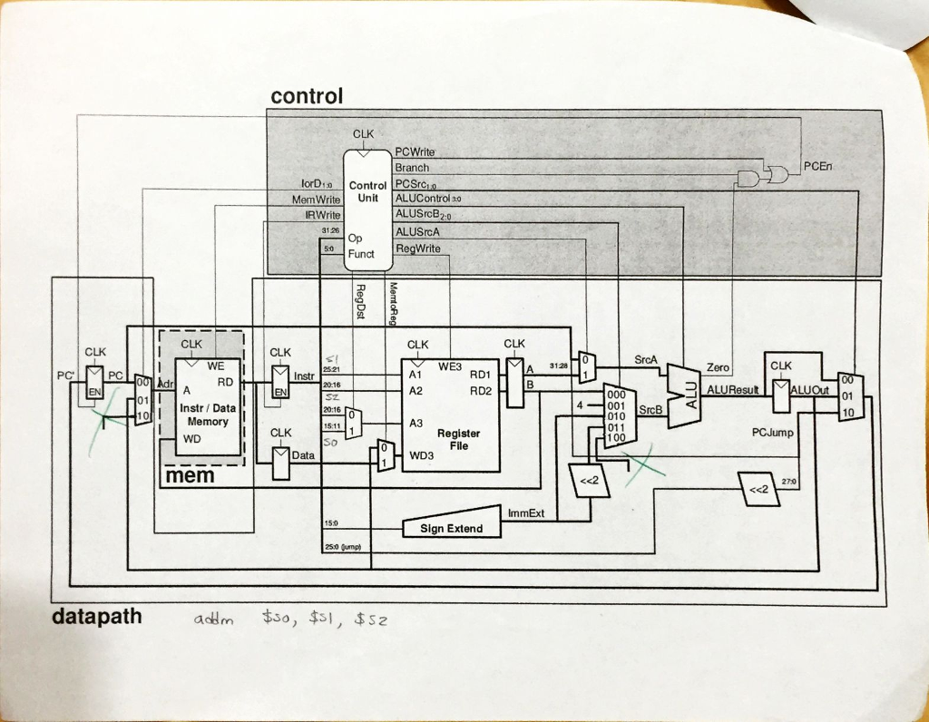
4. Extending the MIPS Hardware You will extend our MIPS hardware to accommodate a new instruction, addm (add from memory). The instruction works similar to an add, taking three registers: However, the difference is that now the third register is a memory address. The addm instruction does the following: MEMs2]. This means that the result that goes into $s0 should be the value in $s1 plus the value in memory at address $s2. (The standard MIPS add would simply do: ss0+2). You can assume the register numbers are stored as in a normal add, so in the above example ss1, s2, sso would respectively be Instr 125:21], [20:161, t15:111. To include this instruction, we must modify both the FSM and the MIPS hardware. For the hardware (on the next page), two multiplexors must be expanded to include new inputs: the one controlled by lorD, and the one controlled by ALUSrcB. The FSM (below, with lorD and ALUSrcB expanded) must now include states for addm. 1. Connect the unconnected components in the hardware on the next page (input 10 of the lorD multiplexor, and input 100 of the ALUSrcB multiplexor). 2. Complete the FSM below, to accommodate the adm instruction. For full credit, add the minimum number of states. ALUS . 011 LUS 000 ALUOg 00 4. Extending the MIPS Hardware You will extend our MIPS hardware to accommodate a new instruction, addm (add from memory). The instruction works similar to an add, taking three registers: However, the difference is that now the third register is a memory address. The addm instruction does the following: MEMs2]. This means that the result that goes into $s0 should be the value in $s1 plus the value in memory at address $s2. (The standard MIPS add would simply do: ss0+2). You can assume the register numbers are stored as in a normal add, so in the above example ss1, s2, sso would respectively be Instr 125:21], [20:161, t15:111. To include this instruction, we must modify both the FSM and the MIPS hardware. For the hardware (on the next page), two multiplexors must be expanded to include new inputs: the one controlled by lorD, and the one controlled by ALUSrcB. The FSM (below, with lorD and ALUSrcB expanded) must now include states for addm. 1. Connect the unconnected components in the hardware on the next page (input 10 of the lorD multiplexor, and input 100 of the ALUSrcB multiplexor). 2. Complete the FSM below, to accommodate the adm instruction. For full credit, add the minimum number of states. ALUS . 011 LUS 000 ALUOg 00
Step by Step Solution
There are 3 Steps involved in it

Get step-by-step solutions from verified subject matter experts