

Question: Implement and explain operations of the quantum error correction circuits in slides 12 and 15. How do they work? Slide 12 Slide 15 Use ancillary
Implement and explain operations of the quantum error correction circuits in slides 12 and 15. How do they work?
Slide 12
Slide 15
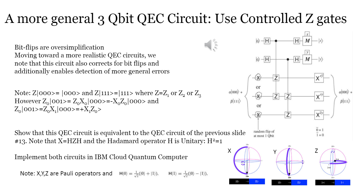
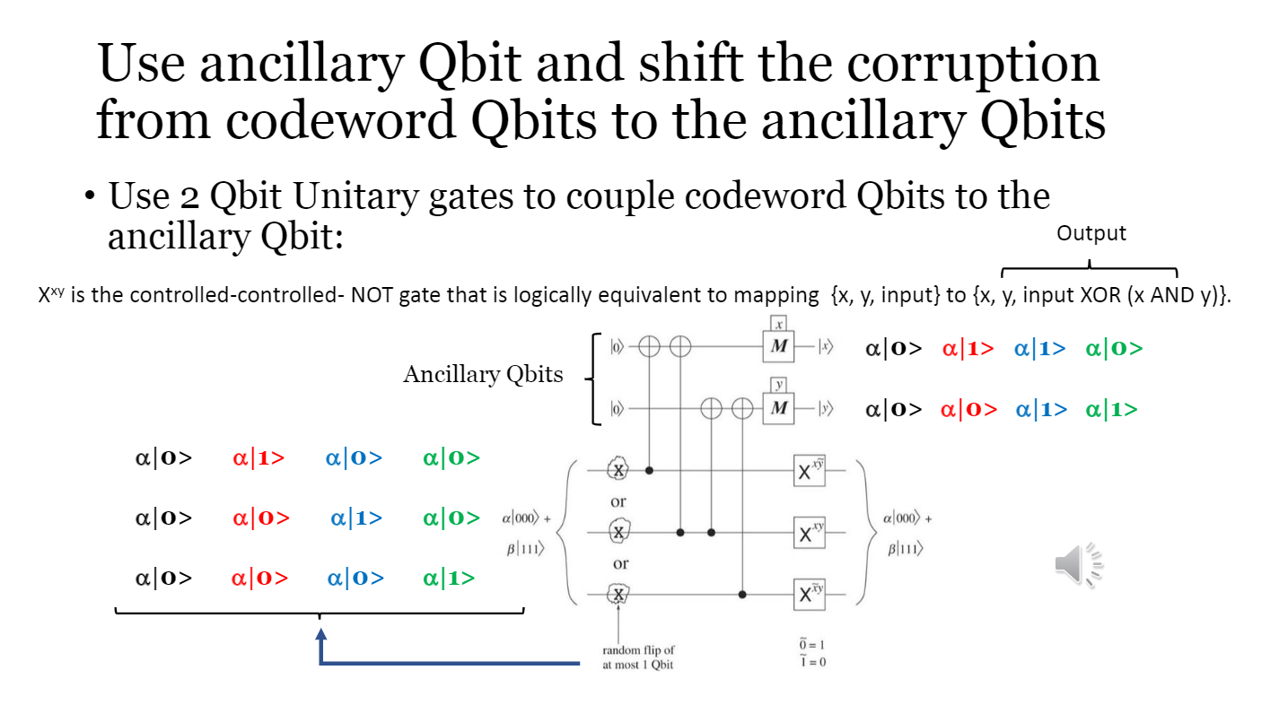
Use ancillary Qbit and shift the corruption from codeword Qbits to the ancillary Qbits Use 2 Qbit Unitary gates to couple codeword Qbits to the ancillary Qbit: Output Xxy is the controlled-controlled- NOT gate that is logically equivalent to mapping {x, y, input} to {x, y, input XOR (X AND y)}. 10) M -18) alo> a[1> a[1> alo> Ancillary Qbits lo M -I) alo> alo> a[1> a[1> alo> a[1> alo> ajo> x" or alo> ao> a[1> X X a|0> a[000) + Blue) a[1> a|000) + B111) or a|0> alo> ao> xy random flip of at most 1 Obit 7 = 1 =0 A more general 3 Qbit QEC Circuit: Use Controlled Z gates lo) H HMX) Bit-flips are oversimplification Moving toward a more realistic QEC circuits, we note that this circuit also corrects for bit flips and additionally enables detection of more general errors lo-H H M -N X or al000) + a|000) + z z x Note: Z|000>= 1000> and Z|111>=|111> where Z=Z, or Z, or Zz However Z.|001>= Z,X, 000>=-X,Z|000> and Z|001>=Z,X, 000>=+X,Z.> Blu) Blu) or X 7 = 1 random flip of at most I Qbit Show that this QEC circuit is equivalent to the QEC circuit of the previous slide #13. Note that X=HZH and the Hadamard operator H is Unitary: H2=1 1 = 0 a> 10 X Y Z 3 Implement both circuits in IBM Cloud Quantum Computer + Note: X,Y,Z are Pauli operators and H|0) = + (10) +11)), H1) = (10) 11), 115 (1) 115 10) 11) 10) (1) Use ancillary Qbit and shift the corruption from codeword Qbits to the ancillary Qbits Use 2 Qbit Unitary gates to couple codeword Qbits to the ancillary Qbit: Output Xxy is the controlled-controlled- NOT gate that is logically equivalent to mapping {x, y, input} to {x, y, input XOR (X AND y)}. 10) M -18) alo> a[1> a[1> alo> Ancillary Qbits lo M -I) alo> alo> a[1> a[1> alo> a[1> alo> ajo> x" or alo> ao> a[1> X X a|0> a[000) + Blue) a[1> a|000) + B111) or a|0> alo> ao> xy random flip of at most 1 Obit 7 = 1 =0 A more general 3 Qbit QEC Circuit: Use Controlled Z gates lo) H HMX) Bit-flips are oversimplification Moving toward a more realistic QEC circuits, we note that this circuit also corrects for bit flips and additionally enables detection of more general errors lo-H H M -N X or al000) + a|000) + z z x Note: Z|000>= 1000> and Z|111>=|111> where Z=Z, or Z, or Zz However Z.|001>= Z,X, 000>=-X,Z|000> and Z|001>=Z,X, 000>=+X,Z.> Blu) Blu) or X 7 = 1 random flip of at most I Qbit Show that this QEC circuit is equivalent to the QEC circuit of the previous slide #13. Note that X=HZH and the Hadamard operator H is Unitary: H2=1 1 = 0 a> 10 X Y Z 3 Implement both circuits in IBM Cloud Quantum Computer + Note: X,Y,Z are Pauli operators and H|0) = + (10) +11)), H1) = (10) 11), 115 (1) 115 10) 11) 10) (1)
Step by Step Solution
There are 3 Steps involved in it

Get step-by-step solutions from verified subject matter experts