

Question: In addition, write a Verilog program to verify your results Textbook Problems 4.13 (p.184) The adder-subtractor circuit of Fig. 4.13 has the following values for
In addition, write a Verilog program to verify your results
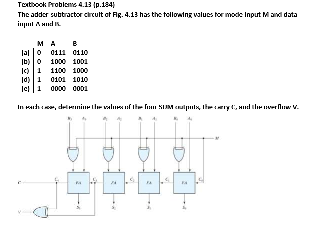
Textbook Problems 4.13 (p.184) The adder-subtractor circuit of Fig. 4.13 has the following values for mode Input M and data input A and B MA B (a)0 0111 0110 (b)0 1000 1001 (c)1 1100 1000 (d) 1 0101 1010 (e) 1 0000 0001 In each case, determine the values of the four SUM outputs, the carry C, and the overflow V. FA FA
Step by Step Solution
There are 3 Steps involved in it
1 Expert Approved Answer
Step: 1 Unlock

Question Has Been Solved by an Expert!
Get step-by-step solutions from verified subject matter experts
Step: 2 Unlock
Step: 3 Unlock