

Question: In Figure 4, the voltage setting is & = 62V, and each resistor is set as R1 = 730, R2 = 1120, R3 = 850.

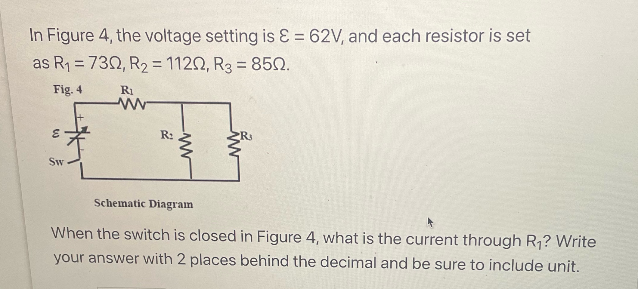
In Figure 4, the voltage setting is & = 62V, and each resistor is set as R1 = 730, R2 = 1120, R3 = 850. Fig. 4 RI 3 R2 R3 SW Schematic Diagram When the switch is closed in Figure 4, what is the current through R1? Write your answer with 2 places behind the decimal and be sure to include unit
Step by Step Solution
There are 3 Steps involved in it
1 Expert Approved Answer
Step: 1 Unlock

Question Has Been Solved by an Expert!
Get step-by-step solutions from verified subject matter experts
Step: 2 Unlock
Step: 3 Unlock