

Question: In Problems 4.1 to 4.6, the input voltage V, is de and positive with the polarity shown. Specify how to implement the switches using
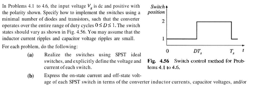
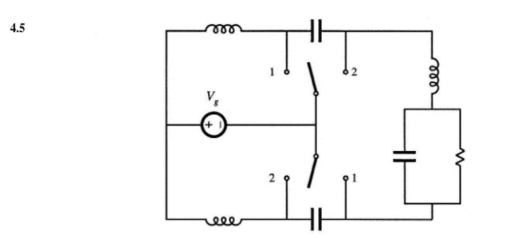
In Problems 4.1 to 4.6, the input voltage V, is de and positive with the polarity shown. Specify how to implement the switches using a minimal number of diodes and transistors, such that the converter operates over the entire range of duty cycles 0DS 1. The switch states should vary as shown in Fig. 4.56. You may assume that the inductor current ripples and capacitor voltage ripples are small. For each problem, do the following: (a) (b) Realize the switches using SPST ideal switches, and explicitly define the voltage and current of each switch. Switch 4 position 2 1 DT, Fig. 4.56 Switch control method for Prob- lems 4.1 to 4.6. 0 t Express the on-state current and off-state volt- age of each SPST switch in terms of the converter inductor currents, capacitor voltages, and/or (c) (d) (e) input source voltage. Solve the converter to determine the inductor currents and capacitor voltages, as in Chapter 2. Determine the polarities of the switch on-state currents and off-state voltages. Do the polarities vary with duty cycle? State how each switch can be realized using transistors and/or diodes, and whether the realiza- tion requires single-quadrant, current-bidirectional two-quadrant, voltage-bidirectional two- quadrant, or four-quadrant switches. 4.5 2 ele
Step by Step Solution
There are 3 Steps involved in it

Get step-by-step solutions from verified subject matter experts