

Question: In the figure below, a compression loading frame is illustrated. The power generated by the electrical motor of uniform supply is transmitted through the
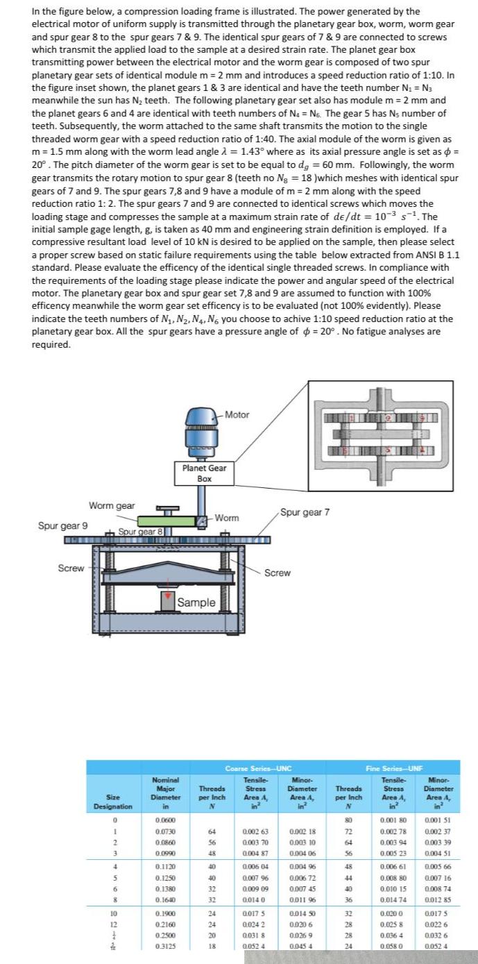
In the figure below, a compression loading frame is illustrated. The power generated by the electrical motor of uniform supply is transmitted through the planetary gear box, worm, worm gear and spur gear 8 to the spur gears 7 & 9. The identical spur gears of 7 & 9 are connected to screws which transmit the applied load to the sample at a desired strain rate. The planet gear box transmitting power between the electrical motor and the worm gear is composed of two spur planetary gear sets of identical module m = 2 mm and introduces a speed reduction ratio of 1:10. In the figure inset shown, the planet gears 1 & 3 are identical and have the teeth number N = N3 meanwhile the sun has N teeth. The following planetary gear set also has module m = 2 mm and the planet gears 6 and 4 are identical with teeth numbers of N = No. The gear 5 has Ns number of teeth. Subsequently, the worm attached to the same shaft transmits the motion to the single threaded worm gear with a speed reduction ratio of 1:40. The axial module of the worm is given as m = 1.5 mm along with the worm lead angle = 1.43 where as its axial pressure angle is set as d = 20. The pitch diameter of the worm gear is set to be equal to dg = 60 mm. Followingly, the worm gear transmits the rotary motion to spur gear 8 (teeth no Ng = 18 )which meshes with identical spur gears of 7 and 9. The spur gears 7,8 and 9 have a module of m= 2 mm along with the speed reduction ratio 1: 2. The spur gears 7 and 9 are connected to identical screws which moves the loading stage and compresses the sample at a maximum strain rate of de/dt = 10--. The initial sample gage length, g, is taken as 40 mm and engineering strain definition is employed. If a compressive resultant load level of 10 kN is desired to be applied on the sample, then please select a proper screw based on static failure requirements using the table below extracted from ANSI B 1.1 standard. Please evaluate the efficency of the identical single threaded screws. In compliance with the requirements of the loading stage please indicate the power and angular speed of the electrical motor. The planetary gear box and spur gear set 7,8 and 9 are assumed to function with 100% efficency meanwhile the worm gear set efficency is to be evaluated (not 100% evidently). Please indicate the teeth numbers of N, N, N4, No you choose to achive 1:10 speed reduction ratio at the planetary gear box. All the spur gears have a pressure angle of = 20. No fatigue analyses are required. Spur gear 9 Screw Worm gear Size Designation Spur gear 8 0 1 2 3 4 5 6 8 10 12 1 2 Nominal Major Diameter in 0.0600 0.0730 0.0860 0.0990 0.1120 0.1250 0.1380 0.1640 0.1900 0.2160 0.2500 0.3125 Planet Gear Box Sample -Motor Worm 64 56 48 40 40 32 32 24 24 20 18 Threads per Inch N HEEGEL Screw Coarse Series-UNC Spur gear 7 Tensile- Stress Area A 2 0.002 63 0.003 70 0.004 87 0.006 04 0.007 96 0.009 09 0.014 0 0.017 5 0.024 2 0031 8 0052 4 Minor- Diameter Area A, in 0.002 18 0.003 10 0.004 06 0.00496 0.006 72 0.007 45 0.011 96 0.014 50 0.020 6 0.026 9 0.045 4 Threads per Inch N 80 72 64 56 48 44 40 36 32 28 28 24 Fine Series-UNF Tensile- Stress Area A in 0.001 80 0.002 78 0.003 94 0.005 23 0.006 61 0.008 80 0.010 15 0.014 74 0.020 0 0.025 8 0.036 4 0.058 0 Minor- Diameter Area A, in 0.001 51 0.002 37 0.003 39 0.004 51 0.005 66 0.007 16 0.008 74 0.012 85 0.017 5 0.022 6 0.032 6 0.052 4
Step by Step Solution
3.48 Rating (158 Votes )
There are 3 Steps involved in it
The efficiency of a worm gear set can be calculated using the formula tantan where is the lead angle ... View full answer

Get step-by-step solutions from verified subject matter experts