

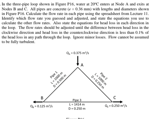
Question: In the three - pipe loop shown in Figure P 1 6 , water at 2 0 C enters at Node A and exits at
In the threepipe loop shown in Figure P water at enters at Node A and exits at
Nodes B and C All pipes are concrete with lengths and diameters shown
in Figure P Calculate the flow rate in each pipe using the spreadsheet from Lecture
Identify which flow rate you guessed and adjusted, and state the equations you use to
calculate the other flow rates. Also state the equations for head loss in each direction in
the loop. The flow rates should be adjusted until the difference between head loss in the
clockwise direction and head loss in the counterclockwise direction is less than of
the head loss in any path through the loop. Ignore minor losses. Flow cannot be assumed
to be fully turbulent.
Step by Step Solution
There are 3 Steps involved in it
1 Expert Approved Answer
Step: 1 Unlock

Question Has Been Solved by an Expert!
Get step-by-step solutions from verified subject matter experts
Step: 2 Unlock
Step: 3 Unlock