

Question: In this part, a MATLAB programming technique will be introduced to generate the animation of the configuration from the previous part of the lab.
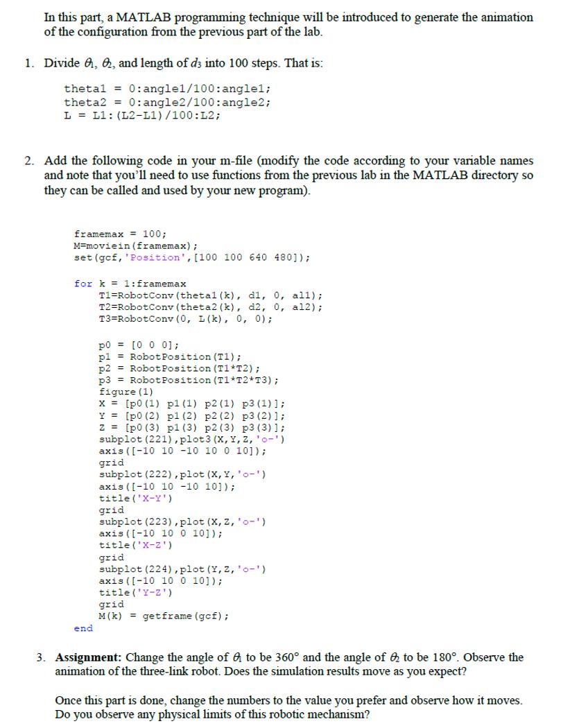
In this part, a MATLAB programming technique will be introduced to generate the animation of the configuration from the previous part of the lab. 1. Divide , &, and length of d3 into 100 steps. That is: thetal = 0: angle1/100: anglel; theta2 = 0:angle2/100: angle2; L = L1: (L2-L1)/100: L2; 2. Add the following code in your m-file (modify the code according to your variable names and note that you'll need to use functions from the previous lab in the MATLAB directory so they can be called and used by your new program). framemax = 100; M-moviein (framemax); set (gcf, 'Position', [100 100 640 480]); for k= 1: framemax end T1 RobotConv (thetal (k), dl, 0, all); T2=RobotConv (theta2 (k), d2, 0, al2); T3 Robot Conv (0, L(k), 0, 0); po [0 0 0]; pl Robot Position (T1); p2 Robot Position (T1*T2); p3 Robot Position (T1*T2*T3); figure (1) x= [p0 (1) pl (1) p2 (1) p3 (1)]; [p0 (2) p1 (2) p2 (2) p3 (2)]; [p0 (3) pl (3) p2 (3) p3 (3)]; subplot (221), plot 3 (X, Y, z, '0'). axis ([-10 10 -10 10 0 10]); grid Y z subplot (222), plot (X, Y, 'o-') axis ([-10 10 -10 101); title ('X-Y') grid subplot (223), plot (X, Z, 'o-) axis ([-10 10 0 10]); title ('X-Z) grid subplot (224), plot (Y, Z, '0-') axis ([-10 10 0 10]); title('Y-Z') grid M (k)= getframe (gof); 3. Assignment: Change the angle of a to be 360 and the angle of 2 to be 180. Observe the animation of the three-link robot. Does the simulation results move as you expect? Once this part is done, change the numbers to the value you prefer and observe how it moves. Do you observe any physical limits of this robotic mechanism?
Step by Step Solution
3.48 Rating (151 Votes )
There are 3 Steps involved in it
It seems like there are some typographical errors and unclear instructions in the provided text Howe... View full answer

Get step-by-step solutions from verified subject matter experts