

Question: In this problem, you will write two Verilog modules. You may describe both modules in the same file. Name your file consistently with the top-level
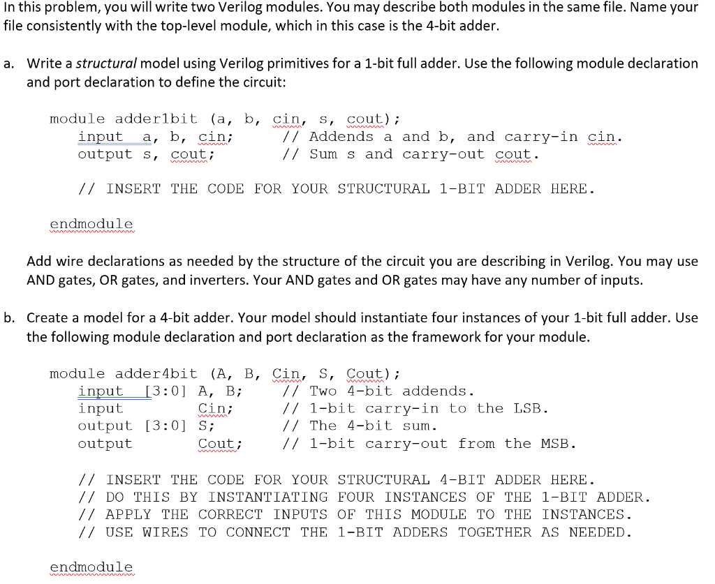
In this problem, you will write two Verilog modules. You may describe both modules in the same file. Name your file consistently with the top-level module, which in this case is the 4-bit adder. Write a structural model using Verilog primitives for a 1-bit full adder. Use the following module declaration and port declaration to define the circuit a. module adderlbit (a, b, cin, s, cout) input a, b, cin,; output s, cout; /7 Addends a and b, and carry-in cin // Sum s and carry-out cout INSERTTHE CODE FOR YOUR STRUCTURAL 1-BIT ADDER HERE endmodule Add wire declarations as needed by the structure of the circuit you are describing in Verilog. You may use AND gates, OR gates, and inverters. Your AND gates and OR gates may have any number of inputs. Create a model for a 4-bit adder. Your model should instantiate four instances of your 1-bit full adder. Use the following module declaration and port declaration as the framework for your module. b. module adder4bit (A, B, Cin, S, Cout); input13:0] A, B; input output [3:0] S; output // Two 4-bit addends // 1-bit carry-in to the LSB //The 4-bit sum. // 1-bit carry-out from the MSB Cin; Cout /INSERT THE CODE FOR YOUR STRUCTURAL 4-BIT ADDER HERE // DO THIS BY INSTANTIATING FOUR INSTANCES OF THE 1-BIT ADDER /APPLY THE CORRECT INPUTS OF THIS MODULE TO THE INSTANCES // USE WIRES TO CONNECT THE 1-BIT ADDERS TOGETHER AS NEEDED endmodule
Step by Step Solution
There are 3 Steps involved in it

Get step-by-step solutions from verified subject matter experts