

Question: In this project, you will design a feasible solution for the shaft of a single - sided grinder. The grinder uses a direct drive (
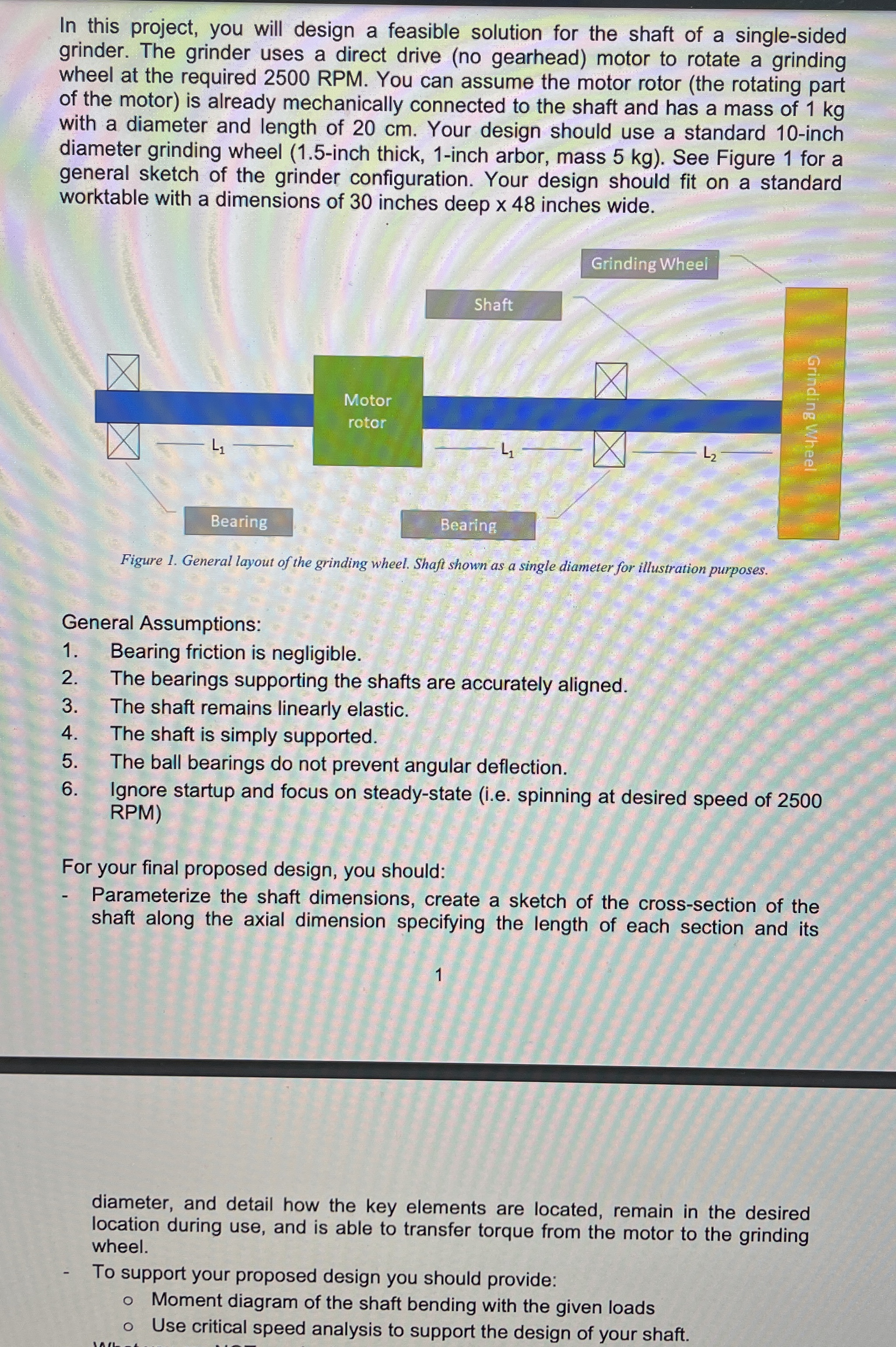
In this project, you will design a feasible solution for the shaft of a singlesided
grinder. The grinder uses a direct drive no gearhead motor to rotate a grinding
wheel at the required RPM You can assume the motor rotor the rotating part
of the motor is already mechanically connected to the shaft and has a mass of kg
with a diameter and length of cm Your design should use a standard inch
diameter grinding wheel inch thick, inch arbor, mass kg See Figure for a
general sketch of the grinder configuration. Your design should fit on a standard
worktable with a dimensions of inches deep inches wide.
General Assumptions:
Bearing friction is negligible.
The bearings supporting the shafts are accurately aligned.
The shaft remains linearly elastic.
The shaft is simply supported.
The ball bearings do not prevent angular deflection.
Ignore startup and focus on steadystate ie spinning at desired speed of
RPM
For your final proposed design, you should:
Parameterize the shaft dimensions, create a sketch of the crosssection of the
shaft along the axial dimension specifying the length of each section and its
diameter, and detail how the key elements are located, remain in the desired
location during use, and is able to transfer torque from the motor to the grinding
wheel.
To support your proposed design you should provide:
Moment diagram of the shaft bending with the given loads
Use critical speed analysis to support the design of your shaft.
Step by Step Solution
There are 3 Steps involved in it
1 Expert Approved Answer
Step: 1 Unlock

Question Has Been Solved by an Expert!
Get step-by-step solutions from verified subject matter experts
Step: 2 Unlock
Step: 3 Unlock