

Question: In VHDL how to implement step one (7 control systems being asked) to a code we already have a code. And implement the MIPS architecture
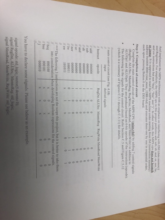
And implement the MIPS architecture with an emphasis on interfacing with DM (data memory) and Registers. For simplicity, the MIPS cpu in this project performs add, sub, slt, and, or, nor, lw and sw instructions but not "beq", "bne" and "j". In other words, this MIPS cpu loss not branch or iump. It is supposed to read the MIPS machine codes starting from IM (instruction memory) 0x0000 0000 (inst mem_128B.vhd) and executes them one by one in sequential order each upon pressing Button 0 on the DEO board. Step 1: Completion of control circuit Complete the main control circuit of the MIPS CPU (mips vhd) by adding 7 control signals (RegDst, ALUSre, MemtoReg, Reg Write, MemRead, and Mem Write) in addition to ALUOpl and ALUOpO. They are produced based on 6-bit opcode of the instruction (opcode). The following is the signals for the control circuit. Refer Section C.5 and Figure C.5.12 (which is a summary of Figures C.5.1 through C.5.11) for details. . // main control circuit (see Fig. 4.18) input derived signals RegDst ALUSre MemtoReg RegWrite MemRead MemWrite Instruct opcode add /sub / slt and 100011 101011 / sw The following 3 instructions are not the scope this project, but it is better to take them / into considertation when developing Boolean expressions for the control signals. // beq //bne 000100 000101 000010 You have to declare some signals. Please see belov signal opcode: std logic_vector(5 downto 0); signal RegDst, ALUSrc, MemtoReg: std signal MemRead, MemWrite, RegWrite
Step by Step Solution
There are 3 Steps involved in it

Get step-by-step solutions from verified subject matter experts