

Question: Include free - body diagrams as needed. Some internal components for a novel torque wrench are shown below. The design premise is that the user
Include freebody diagrams as needed.
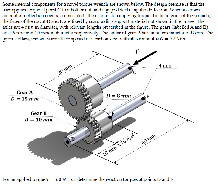
Some internal components for a novel torque wrench are shown below. The design premise is that the
user applies torque at point C to a bolt or nut, and a gage detects angular deflection. When a certain
amount of deflection occurs, a noise alerts the user to stop applying torque. In the interior of the wrench,
the faces of the rod at and are fixed by surrounding support material not shown in the image. The
axles are mm in diameter, with relevant lengths prescribed in the figure. The gears labelled A and B
are mm and mm in diameter respectively. The collar of gear B has an outer diameter of mm The
gears, collars, and axles are all composed of a carbon steel with shear modulus GPa.
For an applied torque determine the reaction torques at points D and E
Step by Step Solution
There are 3 Steps involved in it
1 Expert Approved Answer
Step: 1 Unlock

Question Has Been Solved by an Expert!
Get step-by-step solutions from verified subject matter experts
Step: 2 Unlock
Step: 3 Unlock