

Question: Input Characteristic table to implement Stations 1.7 Stations 5,9 Stations 3.6 0 0 Q 0 0 1 1 0 1 0 1 0 0 0
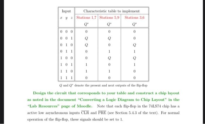
Input Characteristic table to implement Stations 1.7 Stations 5,9 Stations 3.6 0 0 Q 0 0 1 1 0 1 0 1 0 0 0 0 001 Q 0 1 0 Q 0 011 100 Q Q 101 110 1 111 0 0 Qand Q" denoto the present and next outputs of the flip-flop Design the circuit that corresponds to your table and construct a chip layout as noted in the document "Converting a Logic Diagram to Chip Layout" in the "Lab Resources" page of Moodle. Note that each flip-flop in the 74LS74 chip has a active low asynchronous inputs CLR and PRE (see Section 5.4.3 of the text). For normal operation of the flip-flop, these signals should be set to 1. 0 Input Characteristic table to implement Stations 1.7 Stations 5,9 Stations 3.6 0 0 Q 0 0 1 1 0 1 0 1 0 0 0 0 001 Q 0 1 0 Q 0 011 100 Q Q 101 110 1 111 0 0 Qand Q" denoto the present and next outputs of the flip-flop Design the circuit that corresponds to your table and construct a chip layout as noted in the document "Converting a Logic Diagram to Chip Layout" in the "Lab Resources" page of Moodle. Note that each flip-flop in the 74LS74 chip has a active low asynchronous inputs CLR and PRE (see Section 5.4.3 of the text). For normal operation of the flip-flop, these signals should be set to 1. 0
Step by Step Solution
There are 3 Steps involved in it

Get step-by-step solutions from verified subject matter experts