

Question: Instructions: This is a GROUP project to apply Systems Analysis and Development techniques through multiple phases of the Systems Development Life Cycle to complete a
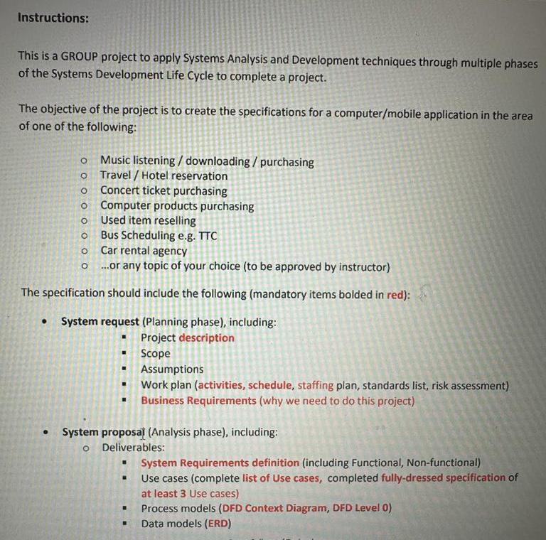
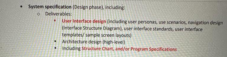
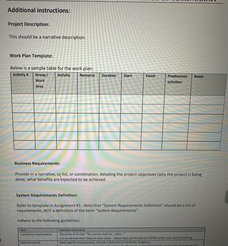
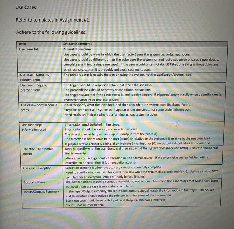
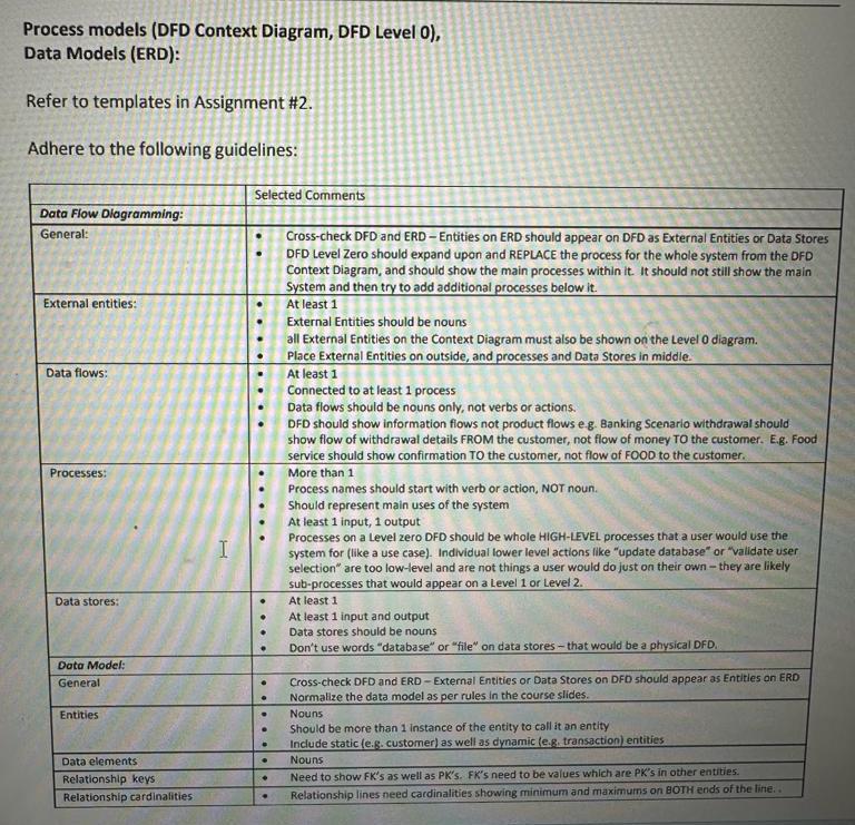
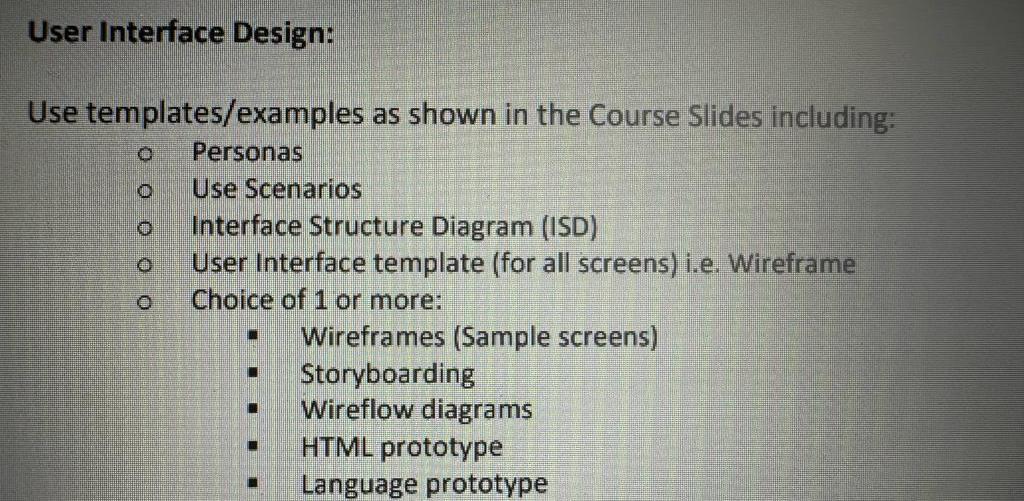
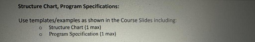
Instructions: This is a GROUP project to apply Systems Analysis and Development techniques through multiple phases of the Systems Development Life Cycle to complete a project. The objective of the project is to create the specifications for a computer/mobile application in the area of one of the following: Music listening / downloading / purchasing Travel / Hotel reservation O Concert ticket purchasing O Computer products purchasing O Used item reselling O Bus Scheduling e.g. TTC Car rental agency o ..or any topic of your choice (to be approved by instructor) The specification should include the following (mandatory items bolded in red): . System request (Planning phase), including: Project description Scope Assumptions Work plan (activities, schedule, staffing plan, standards list, risk assessment) Business Requirements (why we need to do this project) . System proposal (Analysis phase), including: o Deliverables: System Requirements definition (including Functional, Non-functional) Use cases (complete list of Use cases, completed fully-dressed specification of at least 3 Use cases) Process models (DFD Context Diagram, DFD Level 0) Data models (ERD)System specification (Design phase), including: o Deliverables: User Interface design (including user personas, use scenarios, navigation design (Interface Structure Diagram), user interface standards, user interface templates/ sample screen layouts) Architecture design (high-level) Including Structure Chart, and/or Program SpecificationsAdditional instructions: Project Description: This should be a narrative description. Work Plan Template: Below is a sample table for the work plan: Activity # Group / Activity Resource Duration Start Finish Predecessor Notes Work activities Area Business Requirements: Provide in a narrative, or list, or combination, detailing the project objectives (why the project is being done, what benefits are expected to be achieved. System Requirements Definition: Refer to template in Assignment #1. Note that "System Requirements Definition" should be a list of requirements, NOT a definition of the term "System Requirements". Adhere to the following guidelines: Item Selected Comments Functional requirements Should be in format "The system shall do...when." Can be derived from Steps in Uses Cases - select steps performed by SYSTEM when User does something Non-functional Need specific requirements, not just a definition of what the category is.Use Cases: Refer to templates in Assignment #1 Adhere to the following guidelines: Item Selected Comments Use cases list At least 3 use cases. Use cases should be ways in which the user (actor) uses the system Le. verbs, not nouns. Use cases should be different things the actor uses the system for, not just a sequence of steps a user does to complete one thing (a single use case). If the user would or cannot do JUST that one thing without doing any other use cases, then it is probably not a use case on its own. Use case - Name, ID, The primary actor is usually the person using the system, not the application/system itself. Priority, Actor Use case - Trigger, The trigger should be a specific action that starts the use case. preconditions The preconditions should be states or conditions, not actions. The trigger is External if the actor starts it, and is only temporal if triggered automatically when a specific time is reached or amount of time has passed. Use case - normal course Need to specify what the user does, and then also what the system does (back and forth) steps Steps for both user and system both appear under the steps, not some under information. Need to always indicate who is performing action: system or actor. Use case steps - Information must be listed in the steps. Information used Information should be a noun, not an action or verb. The direction must be specified (input or output from the process) The direction is not relative to the user (actor) or relative to the system, It is relative to the use case itself. If graphic arrows are not working, then indicate (1) for input or (O) for output in front of each information. Use case - alternative Need to specify what the user does, and then also what the system does (back and forth). Use case should still course finish normally. Alternative course is generally a variation on the normal course - if the alternative course finishes with a cancellation or error, then it is an exception course. Use case - exception Exception scenario is when the use case cannot successfully complete. Need to specify what the user does, and then also what the system does (back and forth). Use case should NOT complete for an exception, only EXIT early before finished. Post-conditions The postconditions should be states or conditions, not actions. Post-conditions are things that MUST have been achieved if the use case is successfully completed. Inputs/Outputs Summary In the Input/Output summary, the inputs and outputs should match the information In the steps. The Source and Destination should include the primary actor for some of the information. Every use case should have both Inputs and Outputs, otherwise incorrect. "Exit" is not an information.Process models (DFD Context Diagram, DFD Level 0), Data Models (ERD): Refer to templates in Assignment #2. Adhere to the following guidelines: Selected Comments Data Flow Diagramming: General: Cross-check DFD and ERD - Entities on ERD should appear on DFD as External Entities or Data Stores OFD Level Zero should expand upon and REPLACE the process for the whole system from the DFD Context Diagram, and should show the main processes within it. It should not still show the main System and then try to add additional processes below it. External entities: At least 1 External Entities should be nouns all External Entities on the Context Diagram must also be shown on the Level 0 diagram. Place External Entities on outside, and processes and Data Stores in middle. Data flows: At least 1 Connected to at least 1 process Data flows should be nouns only, not verbs or actions. DFD should show information flows not product flows e g. Banking Scenario withdrawal should show flow of withdrawal details FROM the customer, not flow of money TO the customer. E.g. Food service should show confirmation TO the customer, not flow of FOOD to the customer. Processes: More than 1 Process names should start with verb or action, NOT noun. Should represent main uses of the system At least 1 input, 1 output Processes on a Level zero DFD should be whole HIGH-LEVEL processes that a user would use the system for (like a use case). Individual lower level actions like "update database" or "validate user selection" are too low-level and are not things a user would do just on their own - they are likely sub-processes that would appear on a Level 1 or Level 2. Data stores: At least 1 At least 1 input and output Data stores should be nouns Don't use words "database" or "file" on data stores - that would be a physical DFD. Data Model: General Cross-check DFD and ERD - External Entities or Data Stores on DFD should appear as Entitles on ERD Normalize the data model as per rules In the course slides. Entities Nouns Should be more than 1 Instance of the entity to call it an entity Include static (e.g. customer] as well as dynamic (e.g. transaction) entities Data elements Nouns Relationship keys Need to show FK's as well as PK's. FK's need to be values which are PK's in other entities. Relationship cardinalities Relationship lines need cardinalities showing minimum and maximums on BOTH ends of the line. .User Interface Design: Use templates/examples as shown in the Course Slides including: o Personas Use Scenarios Interface Structure Diagram (ISD) User Interface template (for all screens) i.e. Wireframe O Choice of 1 or more: Wireframes (Sample screens) Storyboarding Wireflow diagrams HTML prototype Language prototypeStructure Chart, Program Specifications: Use templates/examples as shown in the Course Slides including: O Structure Chart (1 max) o Program Specification (1 max)
Step by Step Solution
There are 3 Steps involved in it

Get step-by-step solutions from verified subject matter experts