

Question: Internal forces in segments A , B and C . Draw free body diagrams for each case. Use statics. Show the assumed sign convention for
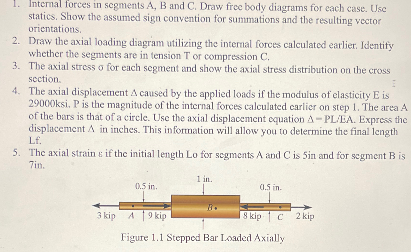
Internal forces in segments A B and C Draw free body diagrams for each case. Use statics. Show the assumed sign convention for summations and the resulting vector orientations.
Draw the axial loading diagram utilizing the internal forces calculated earlier. Identify whether the segments are in tension or compression
The axial stress for each segment and show the axial stress distribution on the cross section.
The axial displacement caused by the applied loads if the modulus of elasticity is ksi. P is the magnitude of the internal forces calculated earlier on step The area A of the bars is that of a circle. Use the axial displacement equation Express the displacement in inches. This information will allow you to determine the final length Lf
The axial strain if the initial length Lo for segments A and is in and for segment is in
Figure stepped Bar Loaded Axally
Step by Step Solution
There are 3 Steps involved in it
1 Expert Approved Answer
Step: 1 Unlock

Question Has Been Solved by an Expert!
Get step-by-step solutions from verified subject matter experts
Step: 2 Unlock
Step: 3 Unlock