

Question: IRF 1 5 0 K p = 2 0 . 5 3 u W = 0 . 3 L = 2 u V t o
IRF
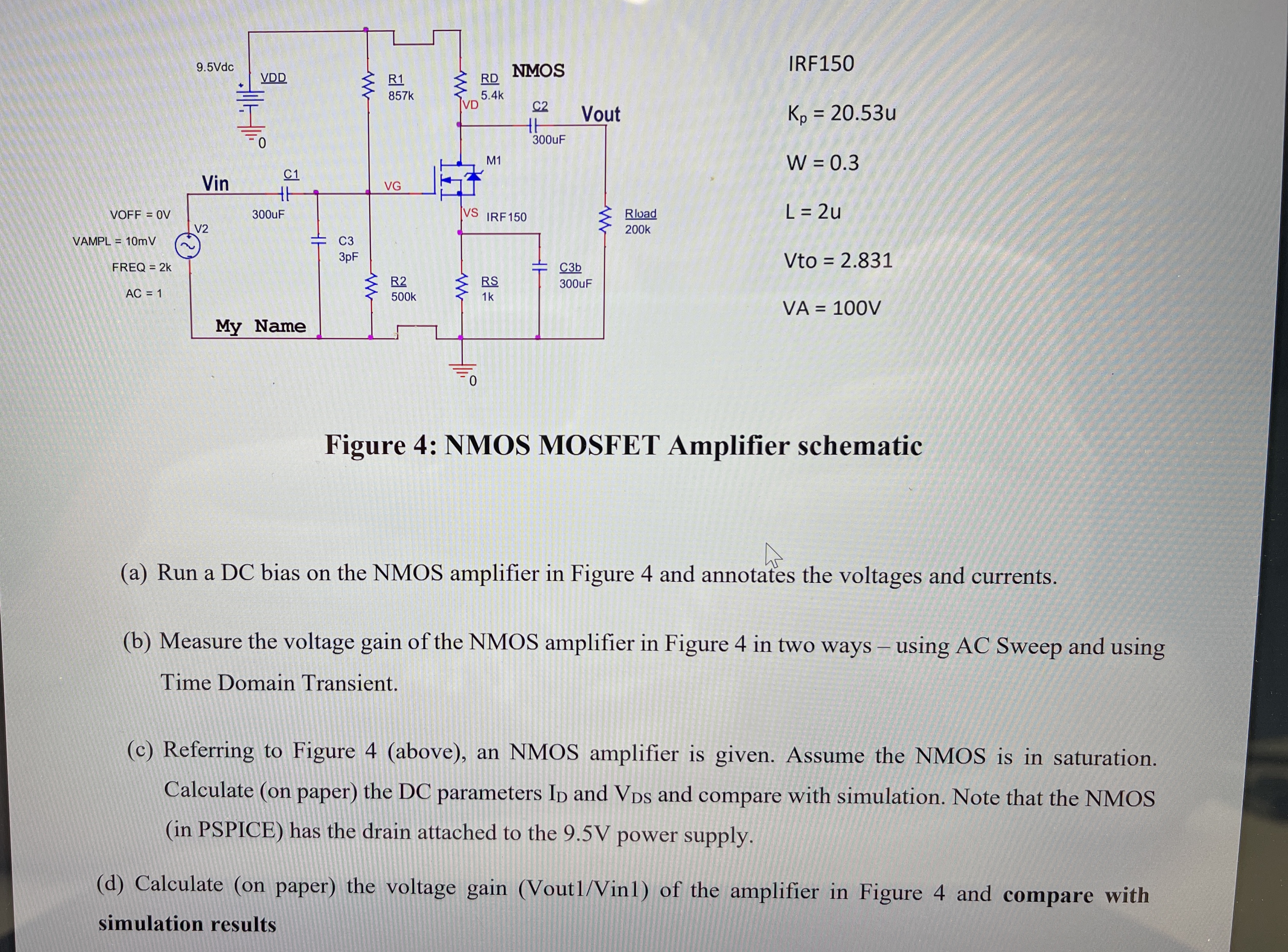
Figure : NMOS MOSFET Amplifier schematic
a Run a DC bias on the NMOS amplifier in Figure and annotates the voltages and currents.
b Measure the voltage gain of the NMOS amplifier in Figure in two ways using AC Sweep and using Time Domain Transient.
c Referring to Figure above an NMOS amplifier is given. Assume the NMOS is in saturation. Calculate on paper the DC parameters and and compare with simulation. Note that the NMOS in PSPICE has the drain attached to the V power supply.
d Calculate on paper the voltage gain VoutVin of the amplifier in Figure and compare with simulation results
Step by Step Solution
There are 3 Steps involved in it
1 Expert Approved Answer
Step: 1 Unlock

Question Has Been Solved by an Expert!
Get step-by-step solutions from verified subject matter experts
Step: 2 Unlock
Step: 3 Unlock