

Question: irning Goal: calculate internal forces in structural members under different loading and port conditions. design a structural member, it is necessary to know the resultant
irning Goal:
calculate internal forces in structural members under different loading and port conditions.
design a structural member, it is necessary to know the resultant forces and nents within the member to ensure the material will be able to support the ling. The method of sections is used to determine internal loadings isider the cantilever beam shown in the image below. Figure
e internal loadings acting on the beam at are to be determined, we make maginary cut at section a perpendicular to the axis of the beam and arate the beam into two segments. The internal loadings at then become ernal on the freebody diagram of each segment, as shown in the image w: Figure
force component acting perpendicular to the cut, or parallel to the axis ne beam, is called the normal force; the force component acting jentially to the cut, or perpendicular to the axis of the beam, is called the ar force; the couple moment is called the bending moment. The forces moments acting on the two segments act in opposite directions, as uired by Newton's third law, and can be determined by applying the ilibrium equations to the freebody diagram of either segment. Provided the ctural member is homogeneous and is not irreversibly deformed, these fings can be considered to act at the centroid of the member's crossion. The customary sign conventions are to say the normal force is positive creates tension, the shear force is positive if it causes the beam segment to te clockwise, and a bending moment is positive if it causes the beam to d concave upward. Oppositelyacting loadings are considered negative.
Part A Internal Loading Due to a Variable, Distributed Load
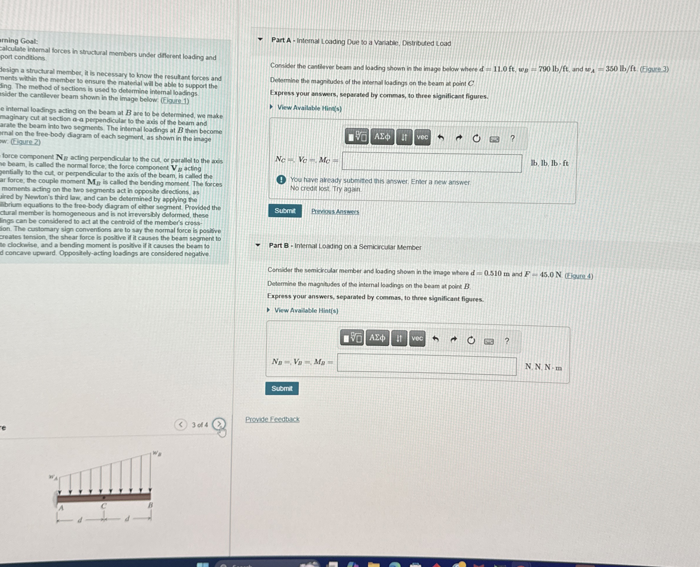
Consider the cantilever beam and loading shown in the image below where and Figure
Determine the magnitudes of the internal loadings on the beam at point
Express your answers, separated by commas, to three significant figures.
View Available Hints
You have already submitted this answer. Enter a new answer.
No credit lost Try again.
Previous Answers
Part B Internal Loading on a Semicircular Member
Consider the semicircular member and loading shown in the image where and Figure
Determine the magnitudes of the internal loadings on the beam at point
Express your answers, separated by commas, to three significant figures.
View Available Hints
Provide Feedback
Step by Step Solution
There are 3 Steps involved in it
1 Expert Approved Answer
Step: 1 Unlock

Question Has Been Solved by an Expert!
Get step-by-step solutions from verified subject matter experts
Step: 2 Unlock
Step: 3 Unlock