

Question: Is this the true circuit? if it's true, than how to prove it. I need the ac and dc analysis of the true circuit for
Is this the true circuit? if it's true, than how to prove it.
I need the ac and dc analysis of the true circuit for this question.
There is no more information in this question.
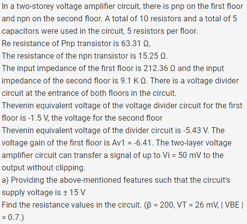
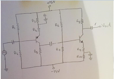
In a two-storey voltage amplifier circuit, there is pnp on the first floor and npn on the second floor. A total of 10 resistors and a total of 5 capacitors were used in the circuit, 5 resistors per floor. Re resistance of Pnp transistor is 63.31 , The resistance of the npn transistor is 15.25 0. The input impedance of the first floor is 212.36 Q and the input impedance of the second floor is 9.1 K 0. There is a voltage divider circuit at the entrance of both floors in the circuit. Thevenin equivalent voltage of the voltage divider circuit for the first floor is -1.5 V, the voltage for the second floor Thevenin equivalent voltage of the divider circuit is -5.43 V. The voltage gain of the first floor is Av1 = -6.41. The two-layer voltage amplifier circuit can transfer a signal of up to Vi = 50 mV to the output without clipping. a) Providing the above-mentioned features such that the circuit's supply voltage is + 15 V Find the resistance values in the circuit. (B = 200, VT = 26 mV, IVBE | = 0.7.) +15V R3 Ri Hho Vout R2 Rg Rg 2103 b -15V In a two-storey voltage amplifier circuit, there is pnp on the first floor and npn on the second floor. A total of 10 resistors and a total of 5 capacitors were used in the circuit, 5 resistors per floor. Re resistance of Pnp transistor is 63.31 , The resistance of the npn transistor is 15.25 0. The input impedance of the first floor is 212.36 Q and the input impedance of the second floor is 9.1 K 0. There is a voltage divider circuit at the entrance of both floors in the circuit. Thevenin equivalent voltage of the voltage divider circuit for the first floor is -1.5 V, the voltage for the second floor Thevenin equivalent voltage of the divider circuit is -5.43 V. The voltage gain of the first floor is Av1 = -6.41. The two-layer voltage amplifier circuit can transfer a signal of up to Vi = 50 mV to the output without clipping. a) Providing the above-mentioned features such that the circuit's supply voltage is + 15 V Find the resistance values in the circuit. (B = 200, VT = 26 mV, IVBE | = 0.7.) +15V R3 Ri Hho Vout R2 Rg Rg 2103 b -15V
Step by Step Solution
There are 3 Steps involved in it

Get step-by-step solutions from verified subject matter experts