

Question: JUST NEED SOLUTION TO PART 2 ! ! ! * * * * * Question 4 ( 3 0 marks - 5 4 minutes )
JUST NEED SOLUTION TO PART
Question marks minutes
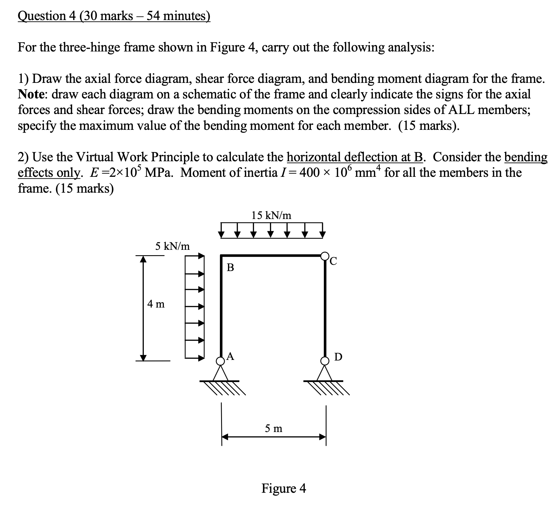
For the threehinge frame shown in Figure carry out the following analysis:
Draw the axial force diagram, shear force diagram, and bending moment diagram for the frame. Note: draw each diagram on a schematic of the frame and clearly indicate the signs for the axial forces and shear forces; draw the bending moments on the compression sides of ALL members; specify the maximum value of the bending moment for each member. marks
Use the Virtual Work Principle to calculate the horizontal deflection at B Consider the bending effects only. MPa. Moment of inertia for all the members in the frame. marks
Figure
Step by Step Solution
There are 3 Steps involved in it
1 Expert Approved Answer
Step: 1 Unlock

Question Has Been Solved by an Expert!
Get step-by-step solutions from verified subject matter experts
Step: 2 Unlock
Step: 3 Unlock