

Question: L and T Inputs Part A: The implementation for this part must use only the three basic logic gates ( AND , OR , NOT
and Inputs
Part A:
The implementation for this part must use only the three basic logic gates AND OR NOT
Each AND gate and each OR gate can have only inputs.
Each NOT gate can have only input.
No other logic gates or circuits are permitted to be used in your circuit for Part A
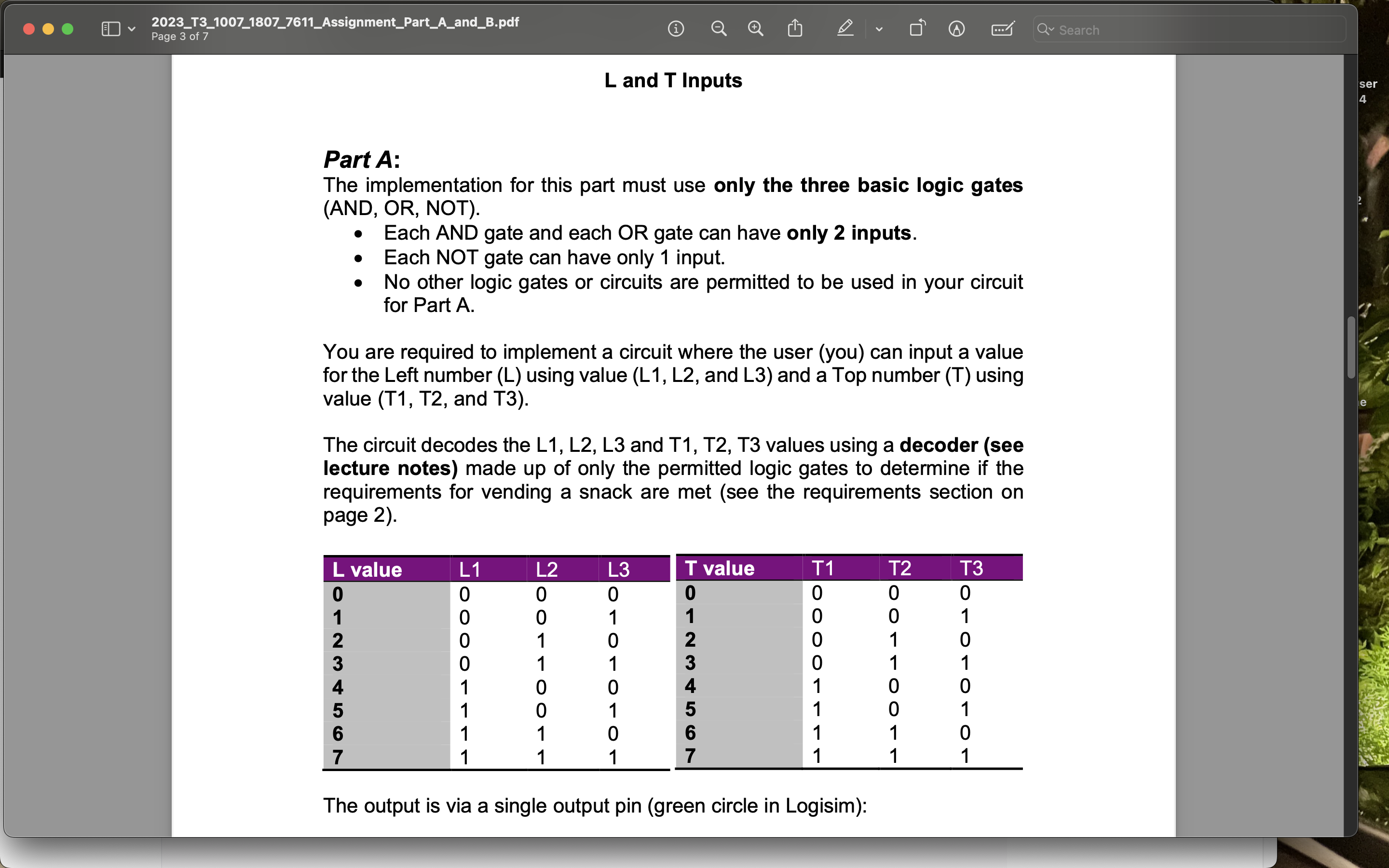
You are required to implement a circuit where the user you can input a value for the Left number using value and and a Top number using value T T and T
The circuit decodes the L L L and T T T values using a decoder see lecture notes made up of only the permitted logic gates to determine if the requirements for vending a snack are met see the requirements section on page
tableL value,LLLT value,TTT
The output is via a single output pin green circle in Logisim:
Step by Step Solution
There are 3 Steps involved in it
1 Expert Approved Answer
Step: 1 Unlock

Question Has Been Solved by an Expert!
Get step-by-step solutions from verified subject matter experts
Step: 2 Unlock
Step: 3 Unlock