

Question: Implement a 4-bit-binary-to-decimal converter on an FPGA board. Use input switches for a binary input. The corresponding decimal number should be displayed on a
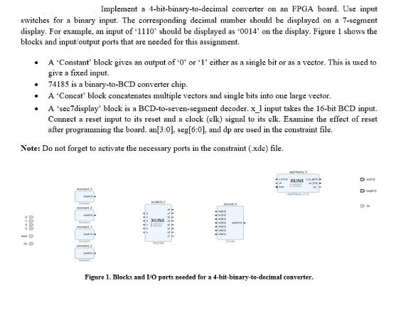
Implement a 4-bit-binary-to-decimal converter on an FPGA board. Use input switches for a binary input. The corresponding decimal number should be displayed on a 7-segment display. For example, an input of '1110' should be displayed as '0014" on the display. Figure 1 shows the blocks and input/output ports that are needed for this assignment. DAZ* A 'Constant' block gives an output of '0' or '1' either as a single bit or as a vector. This is used to give a fixed input. 0000 0.0 . A 'sec7display' block is a BCD-to-seven-segment decoder. x_1 input takes the 16-bit BCD input. Connect a reset input to its reset and a clock (clk) signal to its clk. Examine the effect of reset after programming the board. an[3:0], seg[6:0], and dp are used in the constraint file. Note: Do not forget to activate the necessary ports in the constraint (.xde) file. 74185 is a binary-to-BCD converter chip. A 'Concat' block concatenates multiple vectors and single bits into one large vector. MA WA XILINX Figure 1. Blocks and I/O ports needed for a 4-bit-binary-to-decimal converter. DHE DE De
Step by Step Solution
3.41 Rating (154 Votes )
There are 3 Steps involved in it
The task outlined in the provided document involves implementing a 4bit binary to decimal converter using an FPGA FieldProgrammable Gate Array board H... View full answer

Get step-by-step solutions from verified subject matter experts