

Question: Lab 2: Programming Assignment (modified version of Homework Assignment 2) Write a program to convert the hexadecimal contents of a block of RAM into printable
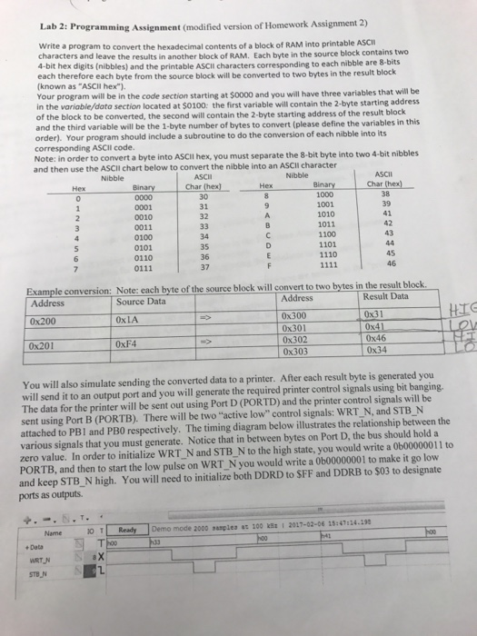
Lab 2: Programming Assignment (modified version of Homework Assignment 2) Write a program to convert the hexadecimal contents of a block of RAM into printable ASCI characters and leave the results in another block of RAM. Each byte in the source block contains two 4-bit hex digits (nibbles) and the printable ASCII characters corresponding to each nibble are 8-bits each therefore each byte from the source block will be converted to two bytes in the result block (known as "ASCII hex"). Your program will be in the code section starting at $oo00 and you will have three variables that will be in the variable/data section located at $0100: the first variable will contain the 2-byte starting address of the block to be converted, the second will contain the 2-byte starting address of the result block and the third variable will be the 1-byte number of bytes to convert (please define the variables in this order). Your progr corresponding ASCII code. Note: in order to convert a byte into ASCII hex, you must separate the 8-bit byte into two 4-bit nibbles and then use the ASCII chart below to convert the nibble into an ASCII character am should include a subroutine to do the conversion of each nibble into its Nibble ASCII Char (hex] 30 31 32 Nibble ASCII Binary 1000 1001 1010 1011 1100 1101 1110 0001 0010 0011 0100 41 0110 0111 35 36 37 46 Example conversion: Note: each byte of the source block will convert to two bytes in the result block Source Data Address 0x200 0x201 Result Data 0x31 0x46 Address 0x300 0x301 0x302 0x303 0xLA 0xF4 You will also simulate sending the converted data to a printer. After each result byte is generated you will send it to an output port and you will generate the required printer control signals using bit banging. The data for the printer will be sent out using Port D (PORTD) and the printer control signals will be sent using Port B (PORTB). There will be two "active low" control signals: WRT_N, and STB N attached to PBI and PB0 respectively. The timing diagram below illustrates the relationship between the various signals that you must generate. Notice that in between bytes on Port D, the bus should hold a zero value. In order to initialize WRT N and STB N to the high state, you would write a 0b00000011 to PORTB, and then to start the low pulse on WRT N you would write a 0b00000001 to make it go low and keep STB N high. You will need to initialize both DDRD to SFF and DDRB to $03 to designate ports as outputs. Name 0 Demo mode 2000 sasples ac 100 kSz2017-02-06 15:47:24.19 Data STBN
Step by Step Solution
There are 3 Steps involved in it

Get step-by-step solutions from verified subject matter experts