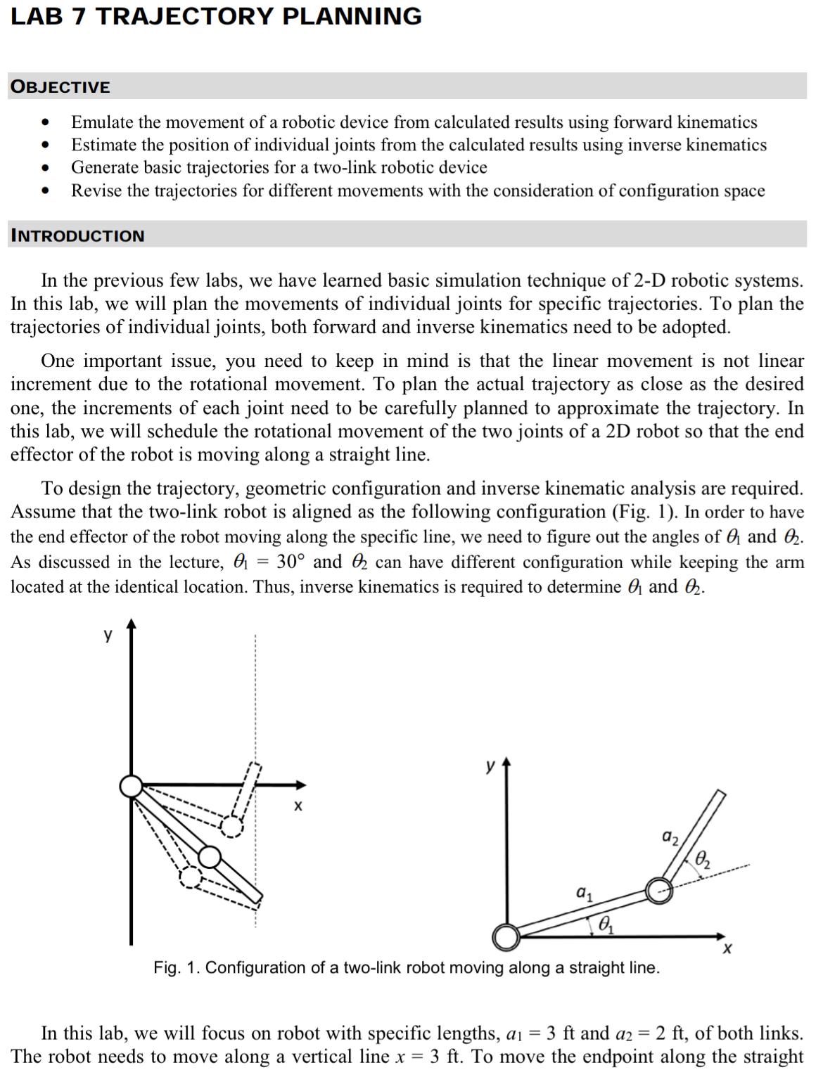
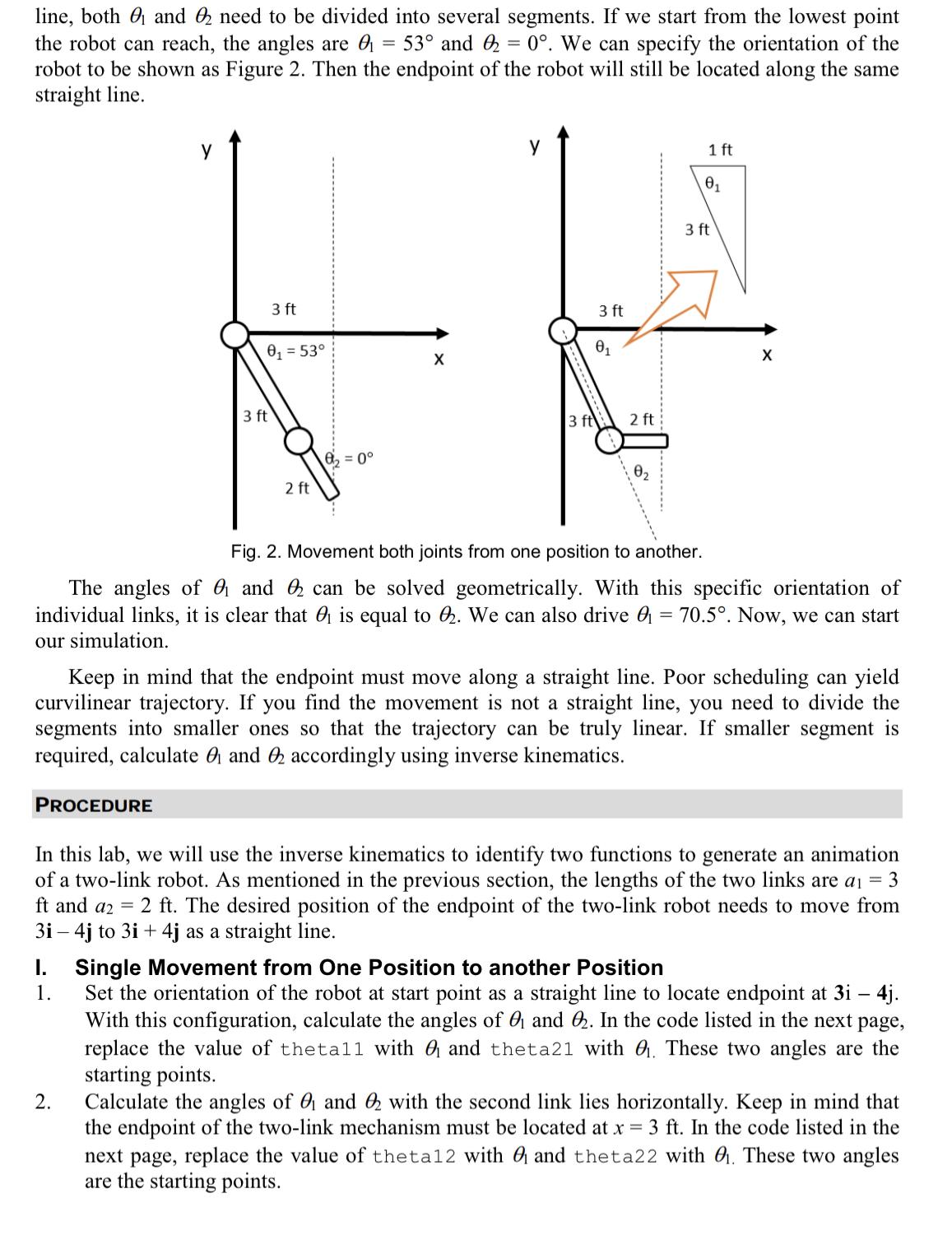
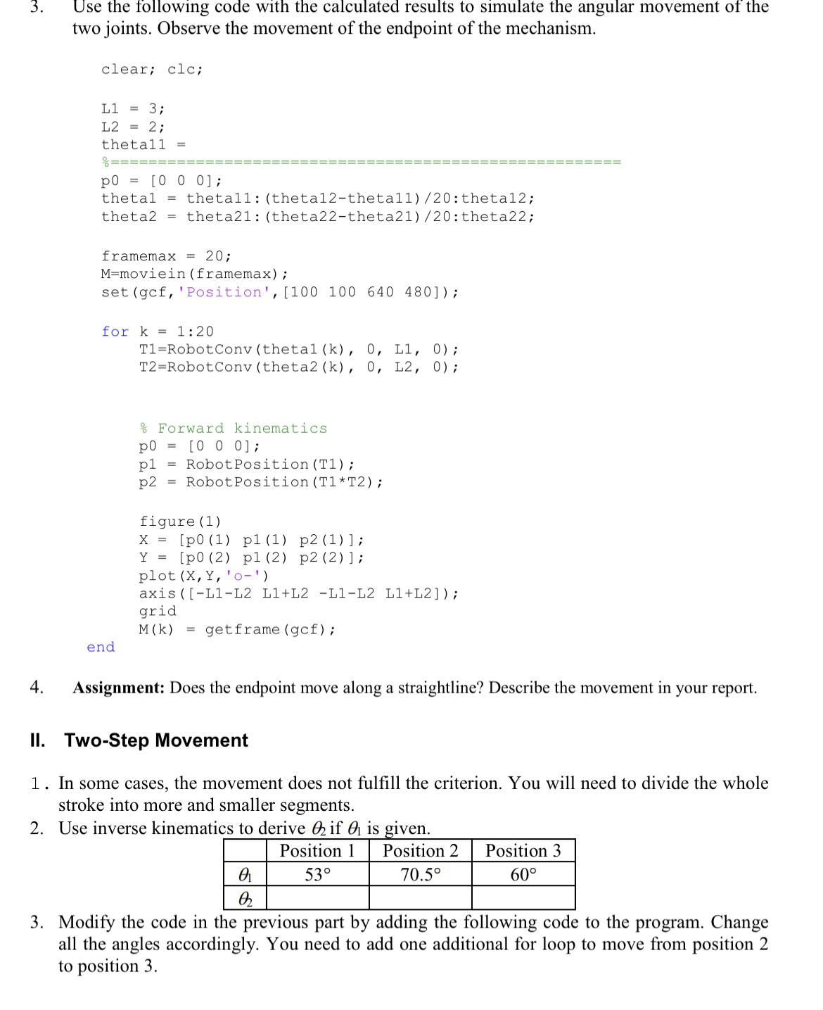
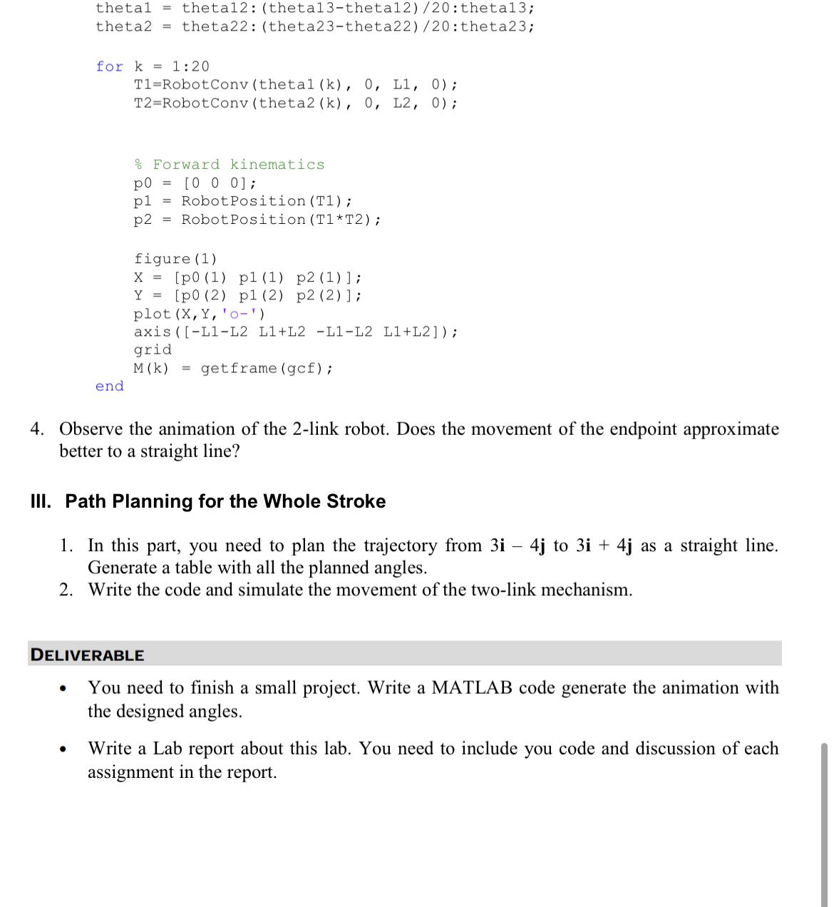
LAB 7 TRAJECTORY PLANNING OBJECTIVE Emulate the movement of a robotic device from calculated...
Fantastic news! We've Found the answer you've been seeking!
Question:
Transcribed Image Text:
LAB 7 TRAJECTORY PLANNING OBJECTIVE ● ● Emulate the movement of a robotic device from calculated results using forward kinematics Estimate the position of individual joints from the calculated results using inverse kinematics Generate basic trajectories for a two-link robotic device Revise the trajectories for different movements with the consideration of configuration space INTRODUCTION In the previous few labs, we have learned basic simulation technique of 2-D robotic systems. In this lab, we will plan the movements of individual joints for specific trajectories. To plan the trajectories of individual joints, both forward and inverse kinematics need to be adopted. One important issue, you need to keep in mind is that the linear movement is not linear increment due to the rotational movement. To plan the actual trajectory as close as the desired one, the increments of each joint need to be carefully planned to approximate the trajectory. In this lab, we will schedule the rotational movement of the two joints of a 2D robot so that the end effector of the robot is moving along a straight line. To design the trajectory, geometric configuration and inverse kinematic analysis are required. Assume that the two-link robot is aligned as the following configuration (Fig. 1). In order to have the end effector of the robot moving along the specific line, we need to figure out the angles of ₁ and 2₂. As discussed in the lecture, 30° and 2 can have different configuration while keeping the arm located at the identical location. Thus, inverse kinematics is required to determine and 2₂. y X a1 0₁ Fig. 1. Configuration of a two-link robot moving along a straight line. 02 X In this lab, we will focus on robot with specific lengths, a₁ = 3 ft and a2 = 2 ft, of both links. The robot needs to move along a vertical line x = 3 ft. To move the endpoint along the straight = line, both and 2 need to be divided into several segments. If we start from the lowest point the robot can reach, the angles are ₁ 53° and 2 = 0°. We can specify the orientation of the robot to be shown as Figure 2. Then the endpoint of the robot will still be located along the same straight line. PROCEDURE y I. 3 ft 0₁ = 53° 1. 3 ft 2. 2 ft 8₂ = 0° X у 3 ft 3 ft 0₁ 2 ft 1 ft Fig. 2. Movement both joints from one position to another. The angles of ₁ and can be solved geometrically. With this specific orientation of individual links, it is clear that ₁ is equal to . We can also drive ₁ = 70.5°. Now, we can start our simulation. 0₁ Keep in mind that the endpoint must move along a straight line. Poor scheduling can yield curvilinear trajectory. If you find the movement is not a straight line, you need to divide the segments into smaller ones so that the trajectory can be truly linear. If smaller segment is required, calculate ₁ and 2 accordingly using inverse kinematics. 3 ft X In this lab, we will use the inverse kinematics to identify two functions to generate an animation of a two-link robot. As mentioned in the previous section, the lengths of the two links are a₁ = 3 ft and a2 = 2 ft. The desired position of the endpoint of the two-link robot needs to move from 3i - 4j to 3i + 4j as a straight line. Single Movement from One Position to another Position Set the orientation of the robot at start point as a straight line to locate endpoint at 3i - 4j. With this configuration, calculate the angles of and 2. In the code listed in the next page, replace the value of the tall with and theta21 with ₁. These two angles are the starting points. Calculate the angles of ₁ and 2 with the second link lies horizontally. Keep in mind that the endpoint of the two-link mechanism must be located at x = 3 ft. In the code listed in the next page, replace the value of theta12 with and theta22 with ₁. These two angles are the starting points. 3. 4. Use the following code with the calculated results to simulate the angular movement of the two joints. Observe the movement of the endpoint of the mechanism. clear; clc; L1 = 3; L2 = 2; thetall p0 = [0 0 0]; thetal theta2 = framemax = 20; M-moviein (framemax) ; set (gcf, 'Position', [100 100 640 480]); thetall: (theta12-theta11) /20: theta12; theta21: (theta 22-theta21) /20: theta22; for k= 1:20 end T1 Robot Conv (thetal (k), 0, L1, 0); T2 Robot Conv (theta2 (k), 0, L2, 0); = % Forward kinematics po [0 0 0]; pl Robot Position (T1); p2 Robot Position (T1 T2); figure (1) X = [p0 (1) p1 (1) p2 (1) ]; Y [p0 (2) pl (2) p2 (2) ] ; plot (X, Y, '0-') axis ([-L1-L2 L1+L2-L1-L2 L1+L2]); grid M (k) = getframe (gcf); Assignment: Does the endpoint move along a straightline? Describe the movement in your report. II. Two-Step Movement 1. In some cases, the movement does not fulfill the criterion. You will need to divide the whole stroke into more and smaller segments. 2. Use inverse kinematics to derive if is given. Position 1 53° 0₁ Q Position 2 Position 3 70.5° 60° 3. Modify the code in the previous part by adding the following code to the program. Change all the angles accordingly. You need to add one additional for loop to move from position 2 to position 3. thetal theta12: (theta13-theta12) /20: theta13; theta2 theta22: (theta23-theta22) /20: theta23; = for k=1:20 end ● T1 Robot Conv (thetal (k), 0, L1, 0); T2 RobotConv (theta2 (k), 0, L2, 0); % Forward kinematics. po = [0 0 0]; pl = Robot Position (T1); p2 Robot Position (T1 T2); figure (1) X= [p0 (1) pl (1) p2 (1)]; Y [p0 (2) p1 (2) p2 (2) ]; plot (X, Y, '0') axis ([-L1-L2 L1+L2 -L1-L2 L1+L2]); grid M (K) = getframe (gcf); 4. Observe the animation of the 2-link robot. Does the movement of the endpoint approximate better to a straight line? III. Path Planning for the Whole Stroke 1. In this part, you need to plan the trajectory from 3i 4j to 3i + 4j as a straight line. Generate a table with all the planned angles. 2. Write the code and simulate the movement of the two-link mechanism. DELIVERABLE You need to finish a small project. Write a MATLAB code generate the animation with the designed angles. Write a Lab report about this lab. You need to include you code and discussion of each assignment in the report. LAB 7 TRAJECTORY PLANNING OBJECTIVE ● ● Emulate the movement of a robotic device from calculated results using forward kinematics Estimate the position of individual joints from the calculated results using inverse kinematics Generate basic trajectories for a two-link robotic device Revise the trajectories for different movements with the consideration of configuration space INTRODUCTION In the previous few labs, we have learned basic simulation technique of 2-D robotic systems. In this lab, we will plan the movements of individual joints for specific trajectories. To plan the trajectories of individual joints, both forward and inverse kinematics need to be adopted. One important issue, you need to keep in mind is that the linear movement is not linear increment due to the rotational movement. To plan the actual trajectory as close as the desired one, the increments of each joint need to be carefully planned to approximate the trajectory. In this lab, we will schedule the rotational movement of the two joints of a 2D robot so that the end effector of the robot is moving along a straight line. To design the trajectory, geometric configuration and inverse kinematic analysis are required. Assume that the two-link robot is aligned as the following configuration (Fig. 1). In order to have the end effector of the robot moving along the specific line, we need to figure out the angles of ₁ and 2₂. As discussed in the lecture, 30° and 2 can have different configuration while keeping the arm located at the identical location. Thus, inverse kinematics is required to determine and 2₂. y X a1 0₁ Fig. 1. Configuration of a two-link robot moving along a straight line. 02 X In this lab, we will focus on robot with specific lengths, a₁ = 3 ft and a2 = 2 ft, of both links. The robot needs to move along a vertical line x = 3 ft. To move the endpoint along the straight = line, both and 2 need to be divided into several segments. If we start from the lowest point the robot can reach, the angles are ₁ 53° and 2 = 0°. We can specify the orientation of the robot to be shown as Figure 2. Then the endpoint of the robot will still be located along the same straight line. PROCEDURE y I. 3 ft 0₁ = 53° 1. 3 ft 2. 2 ft 8₂ = 0° X у 3 ft 3 ft 0₁ 2 ft 1 ft Fig. 2. Movement both joints from one position to another. The angles of ₁ and can be solved geometrically. With this specific orientation of individual links, it is clear that ₁ is equal to . We can also drive ₁ = 70.5°. Now, we can start our simulation. 0₁ Keep in mind that the endpoint must move along a straight line. Poor scheduling can yield curvilinear trajectory. If you find the movement is not a straight line, you need to divide the segments into smaller ones so that the trajectory can be truly linear. If smaller segment is required, calculate ₁ and 2 accordingly using inverse kinematics. 3 ft X In this lab, we will use the inverse kinematics to identify two functions to generate an animation of a two-link robot. As mentioned in the previous section, the lengths of the two links are a₁ = 3 ft and a2 = 2 ft. The desired position of the endpoint of the two-link robot needs to move from 3i - 4j to 3i + 4j as a straight line. Single Movement from One Position to another Position Set the orientation of the robot at start point as a straight line to locate endpoint at 3i - 4j. With this configuration, calculate the angles of and 2. In the code listed in the next page, replace the value of the tall with and theta21 with ₁. These two angles are the starting points. Calculate the angles of ₁ and 2 with the second link lies horizontally. Keep in mind that the endpoint of the two-link mechanism must be located at x = 3 ft. In the code listed in the next page, replace the value of theta12 with and theta22 with ₁. These two angles are the starting points. 3. 4. Use the following code with the calculated results to simulate the angular movement of the two joints. Observe the movement of the endpoint of the mechanism. clear; clc; L1 = 3; L2 = 2; thetall p0 = [0 0 0]; thetal theta2 = framemax = 20; M-moviein (framemax) ; set (gcf, 'Position', [100 100 640 480]); thetall: (theta12-theta11) /20: theta12; theta21: (theta 22-theta21) /20: theta22; for k= 1:20 end T1 Robot Conv (thetal (k), 0, L1, 0); T2 Robot Conv (theta2 (k), 0, L2, 0); = % Forward kinematics po [0 0 0]; pl Robot Position (T1); p2 Robot Position (T1 T2); figure (1) X = [p0 (1) p1 (1) p2 (1) ]; Y [p0 (2) pl (2) p2 (2) ] ; plot (X, Y, '0-') axis ([-L1-L2 L1+L2-L1-L2 L1+L2]); grid M (k) = getframe (gcf); Assignment: Does the endpoint move along a straightline? Describe the movement in your report. II. Two-Step Movement 1. In some cases, the movement does not fulfill the criterion. You will need to divide the whole stroke into more and smaller segments. 2. Use inverse kinematics to derive if is given. Position 1 53° 0₁ Q Position 2 Position 3 70.5° 60° 3. Modify the code in the previous part by adding the following code to the program. Change all the angles accordingly. You need to add one additional for loop to move from position 2 to position 3. thetal theta12: (theta13-theta12) /20: theta13; theta2 theta22: (theta23-theta22) /20: theta23; = for k=1:20 end ● T1 Robot Conv (thetal (k), 0, L1, 0); T2 RobotConv (theta2 (k), 0, L2, 0); % Forward kinematics. po = [0 0 0]; pl = Robot Position (T1); p2 Robot Position (T1 T2); figure (1) X= [p0 (1) pl (1) p2 (1)]; Y [p0 (2) p1 (2) p2 (2) ]; plot (X, Y, '0') axis ([-L1-L2 L1+L2 -L1-L2 L1+L2]); grid M (K) = getframe (gcf); 4. Observe the animation of the 2-link robot. Does the movement of the endpoint approximate better to a straight line? III. Path Planning for the Whole Stroke 1. In this part, you need to plan the trajectory from 3i 4j to 3i + 4j as a straight line. Generate a table with all the planned angles. 2. Write the code and simulate the movement of the two-link mechanism. DELIVERABLE You need to finish a small project. Write a MATLAB code generate the animation with the designed angles. Write a Lab report about this lab. You need to include you code and discussion of each assignment in the report.
Expert Answer:
Answer rating: 100% (QA)
Function to convert joint angles to homogeneous transformation matrix function T RobotConvtheta d a alpha T costheta sinthetacosalpha sinthetasinalpha ... View the full answer
Related Book For
Posted Date:
Students also viewed these computer engineering questions
-
A particle moving along a straight line has an acceleration which varies according to position as shown. If the velocity of the particle at the position x = 5 ft is v = 2 ft/sec, determine the...
-
A meteorologist tracks the movement of a thunderstorm with Doppler radar. At 8: 00 PM, the storm was 60 mi northeast of her station. At 10:00 PM, the storm is at 75 mi north. (a) The general...
-
If the velocity v of a particle moving along a straight line decreases linearly with its displacement s from 20 m/s to a value approaching zero at s = 30 m, determine the acceleration a of the...
-
Given the definition of the radian angle: S l Where [s] = m, [4] = m What are the dimensions of angles? A. No way to know B. meters, m C. 1 (or no units/dimensions) D. seconds, S E. kilograms, kg
-
E. F. Lynch Company is a diversified investment company with three operating divisions organized as investment centers. Condensed data taken from the records of the three divisions for the year ended...
-
Integrate the following function analytically and using the trapezoidal rule, with n = 1, 2, 3, and 4: Use the analytical solution to compute true percent relative errors to evaluate the accuracy of...
-
Where does this second rigid-body mode appear due to an equivalent support stiffness of 300,000 lb/inch?
-
Following are two years of income statements and balance sheets for the Munich Exports Corporation. A. Calculate the cash build, cash burn, and net cash burn or build for Munich Exports in 2010. B....
-
An adult helping her child learn to ride a bike, applies a net force of 4.32 newtons to the child on the bike for 2.40 seconds. How much momentum does the child and his bike gain after being pushed...
-
Mr. Geoffrey Guo had a variety of transactions during the 2019 year. Determine the total taxable capital gains included in Mr. Guo's division B income. The transactions included:? 1. On January 1,...
-
Daniel and Wendy formed the XYZ Partnership 8 years ago as a general partnership and have done very well with the business. In this current year, however, economic conditions caused them to lose...
-
On January 1, 2021, Monty Property Management Inc. introduced a stock-based compensation plan for its senior executives. The company has a December 31, 2021 year-end and the following events...
-
Chris and Amy are married and will file a joint tax return. Amy is a 50% partner in A&A Partnership (not a "specified services" business). She received qualified business income of $300,000 from A&A....
-
Evaluate the role of dystopian fiction in reflecting societal fears and concerns. What are the common tropes of this genre, and how do different authors use them to critique contemporary issues ?
-
How does hypertextual fiction transform traditional storytelling? Consider the interactive nature of hypertext and discuss its implications for narrative structure, reader agency, and storytelling...
-
An LC series circuit is comprised of a 1 . 0 - mF capacitor in series with an inductor. The period of electromagnetic oscillations in this circuit is 1 0 0 ms. What is the inductance of the inductor?
-
Windows feature that allows a user to access system tools that require administrative privileges 1) Act as 2) Start as 3) Sudo 4) Run as
-
Dawson Companys balance sheet information at the end of 2019 and 2020 is as follows: Additional information: The company did not issue any common stock during 2020. Required : Next Level Fill in the...
-
A gambling book recommends the following winning strategy for the game of roulette: Bet $1 on red. If red appears (which has probability 18/38), then take the $1 profit and quit. If red does not...
-
If 101 items are distributed among 10 boxes, then at least one of the boxes must contain more than 10 items. Use the probabilistic method to prove this result.
-
Ninety-eight percent of all babies survive delivery. However, 15 percent of all births involve Cesarean (C) sections, and when a C section is performed, the baby survives 96 percent of the time. If a...
-
If a shipment is needed in week 8 and the lead time on its arrival is always 3 weeks, when should the shipment be ordered?
-
If item Y is the parent of Z and item X is the parent of Y, which item is the finished good?
-
Maynard Associates has 62 units of a certain product on hand currently. The demand forecast for the next two planning periods is 25 units each period. Maynard Associ- ates has no plans for production...
Study smarter with the SolutionInn App