

Question: lab information provided to answer procedure question link for information on chapter https://drive.google.com/file/d/1JWHXKVjKbks4fO8WMSf9aE3jUfFhKlG5/view?usp=sharing lab data Ninner = 235, Nouter = 2920 step-up with core (inner


lab information provided to answer procedure question
link for information on chapter https://drive.google.com/file/d/1JWHXKVjKbks4fO8WMSf9aE3jUfFhKlG5/view?usp=sharing
lab data
Ninner = 235, Nouter = 2920 step-up with core (inner primary, outer secondary): VP = 0.200 V, VS = 2.410 V step-up without core (inner primary, outer secondary): VP = 0.200 V, VS = 2.120 V step-down with core (outer primary, inner secondary): VP = 2.000 V, VS = 0.149 V step-down without core (outer primary, inner secondary): VP = 2.000 V, VS = 0.12
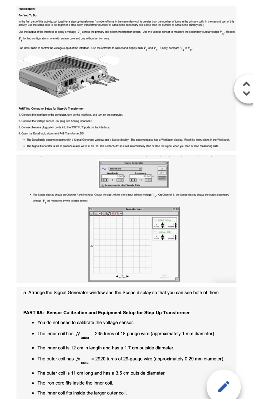
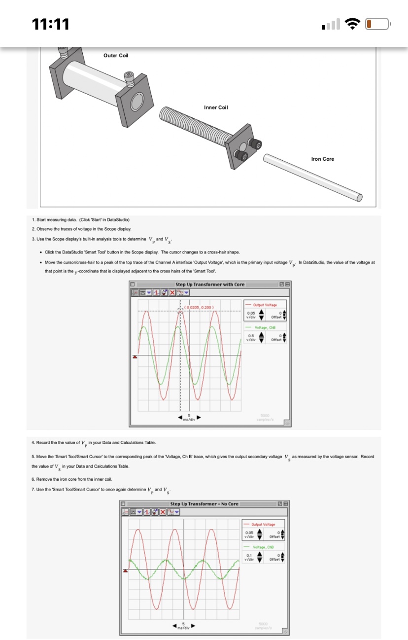
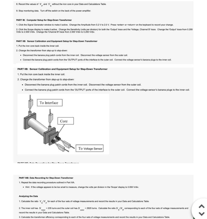

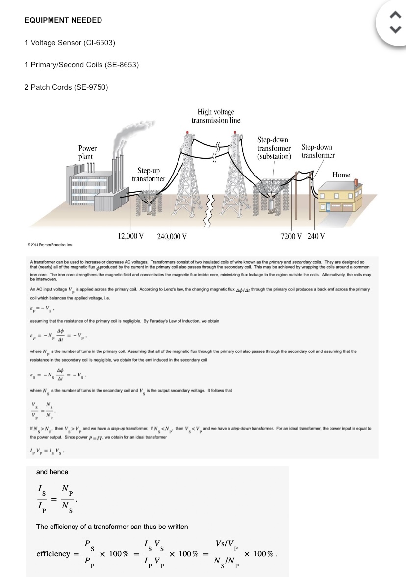
PROCEDURE For You To Do In the first part of this activity, put together a step-up transformer (number of turns in the secondary coll is greater than the number of turns in the primary coil). In the second part of this activity, use the same coils to put together a step-down transformer (number of turns in the secondary coil is less than the number of turns in the primary coil.) Use the output of the interface to apply a voltage \\ across the primary coil in both transformer setups. Use the voltage sensor to measure the secondary output voltage V . Record V for two configurations: one with an iron core and one without an iron core. Use DataStudio to control the voltage output of the interface. Use the software to collect and display both V, and V . Finally, compare V to V PART IA: Computer Setup for Step-Up Transformer 1. Connect the interface to the computer, turn on the interface, and turn on the computer. 2. Connect the voltage sensor DIN plug into Analog Channel B. 3. Connect banana plug patch cords into the 'OUTPUT ports on the interface. 4. Open the DataStudio document P49 Transformer.DS . The DataStudio document opens with a Signal Generator window and a Scope display. The document also has a Workbook display. Read the instructions in the Workbook. . The Signal Generator is set to produce a sine wave at 60 Hz. It is set to 'Auto' so it will automaticaly start or stop the signal when you start or stop measuring data. Signal Generator Our Sine Wave Frequency 0 200 AUTO . The Scope display shows on Channel A the interface 'Output Voltage', which is the input primary voltage V. On Channel B. the Scope display shows the output secondary voltage V as measured by the voltage sensor. Transformer 2 1 8 X 5. Arrange the Signal Generator window and the Scope display so that you can see both of them. PART IIA: Sensor Calibration and Equipment Setup for Step-Up Transformer . You do not need to calibrate the voltage sensor. . The inner coil has N = 235 turns of 18-gauge wire (approximately 1 mm diameter). inner . The inner coil is 12 cm in length and has a 1.7 cm outside diameter. . The outer coil has N = 2920 turns of 29-gauge wire (approximately 0.29 mm diameter). outer . The outer coil is 11 cm long and has a 3.5 cm outside diameter. . The iron core fits inside the inner coil. . The inner coil fits inside the larger outer coil.11:11 Outer Coil Inner Coil Iron Core 1. Start measuring data. (Click 'Start' in DataStudio) 2. Observe the traces of voltage in the Scope display. 3. Use the Scope display's built-in analysis tools to determine V, and V . Click the DataStudio "Smart Tool' button in the Scope display. The cursor changes to a cross-hair shape. Move the cursor/cross-hair to a peak of the top trace of the Channel A interface 'Output Voltage', which is the primary input voltage V. In DataStudio, the value of the voltage at that point is the y-coordinate that is displayed adjacent to the cross hairs of the "Smart Tool. Step Up Transformer with Core 21 X (0 0205, 0.200 - Output Voltage 0.05 w/div Voltage, Che w/div 5000 4. Record the the value of V. in your Data and Calculations Table. 5. Move the "Smart Tool/Smart Cursor' to the corresponding peak of the 'Voltage, Ch B' trace, which gives the output secondary voltage V. as measured by the voltage sensor. Record the value of V. in your Data and Calculations Table. 6. Remove the iron core from the inner coil. 7. Use the "Smart Tool/Smart Cursor' to once again determine V and V Step Up Transformer - No Core DE - Output Voltage 0.05 Voltage, CAB 5000 ma/div Turgles/#QUESTION 2 Procedure: Explain in your own words how your experiment will test the hypothesis or hypotheses. In other words, describe a) the experimental setup, b) what you will measure directly, c) how you will make those direct measurements, and d) how you will obtain your experimental result or results from those direct measurements. Your explanation should be understandable to a member of the physics community who is not familiar with your experiment.8. Record the values of V, and V. without the iron core in your Data and Calculations Table. 9. Stop monitoring data. Turn off the switch on the back of the power amplifier. PART IB: Computer Setup for Step-Down Transformer 1. Click the Signal Generator window to make it active. Change the Amplitude from 0.2 V to 2.0 V. Press center> or return> on the keyboard to record your change. 2. Click the Scope display to make it active. Change the Sensitivity (volts per division) for both the "Output trace and the "Voltage, Channel B' trace. Change the "Output" trace from 0.200 Vidiv to 2 000 Vidiv. Change the "Channel B' trace from 2.000 Vidiv to 0.200 Vidiv. PART IIB: Sensor Calibration and Equipment Setup for Step-Down Transformer 1. Put the iron core back inside the inner coil 2. Change the transformer from stop-up to stop-down: Disconnect the banana plug patch cords from the inner coil. Disconnect the voltage sensor from the outer coil. . Connect the banana plug patch cords from the 'OUTPUT ports of the interface to the outer col. Connect the voltage sensor's banana plugs to the inner call. PART IIB: Sensor Calibration and Equipment Setup for Step-Down Transformer 1. Put the iron core back inside the inner col. 2. Change the transformer from step-up to step-down: . Disconnect the banana plug patch cords from the inner coil. Disconnect the voltage sensor from the outer coil. . Connect the banana plug patch cords from the 'OUTPUT ports of the interface to the outer col. Connect the voltage sensor's banana plugs to the inner coil. To Interface Core To Voltage Sensor PART IIB: Data Recording for Step-Down Transformer 1. Repeat the data recording procedure outlined in Part IIIA. * Hint: if the voltage appears to be too small to measure, change the volts per division in the "Scope" display to 0.050 Vidiv. Analyzing the Data 1. Calculate the ratio V / V for each of the four sets of voltage measurements and record the results in your Data and Calculations Table. 2. The inner coil has NV. = 235 tums and the outer coil has N outer -2920 tums. Calculate the ratio / /N, corresponding to each of the four sets of voltage measurements and record the results in your Data and Calculations Table 3. Calculate the transformer efficiency corresponding to each of the four sets of voltage measurements and record the results in your Data and Calculations Table.EQUIPMENT NEEDED 1 Voltage Sensor (CI-6503) 1 Primary/Second Coils (SE-8653) 2 Patch Cords (SE-9750) High voltage transmission line Step-down Power transformer Step-down plant (substation) transformer Step-up transformer Home 12,000 V 240,000 V 7200 V 240 V @2014 Pearson Education, Inc. A transformer can be used to increase or decrease AC voltages. Transformers consist of two insulated coils of wire known as the primary and secondary coils. They are designed so that (nearly) all of the magnetic flux ; produced by the current in the primary coil also passes through the secondary coil. This may be achieved by wrapping the coils around a common iron core. The iron core strengthens the mag trates the magnetic flux inside core, minimizing flux leakage to the region outside the coils. Alternatively, the coils may be interwoven. An AC input voltage V, is applied across the primary coil. According to Lenz's law, the changing magnetic flux Ap/ Ar through the primary coil produces a back omf across the primary coil which balances the applied voltage, i.e. assuming that the resistance of the primary coil is negligible. By Faraday's Law of Induction, we obtain .= -N -= -VP. where /, is the number of turns in the primary coil. Assuming that all of the magnetic flux through the primary coil also passes through the secondary col and assuming that the resistance in the secondary coll is negligible, we obtain for the emf induced in the secondary coll ES = -NS AT -= -VS. where / is the number of turns in the secondary col and V. is the output secondary voltage. It follows that I N. > N . then V. > V and we have a stop-up transformer. If N.
Step by Step Solution
There are 3 Steps involved in it

Get step-by-step solutions from verified subject matter experts