

Question: Learning Goal: To analyze and design a passive, second - order bandreject filter using a series ( R L C ) circuit. A
Learning Goal:
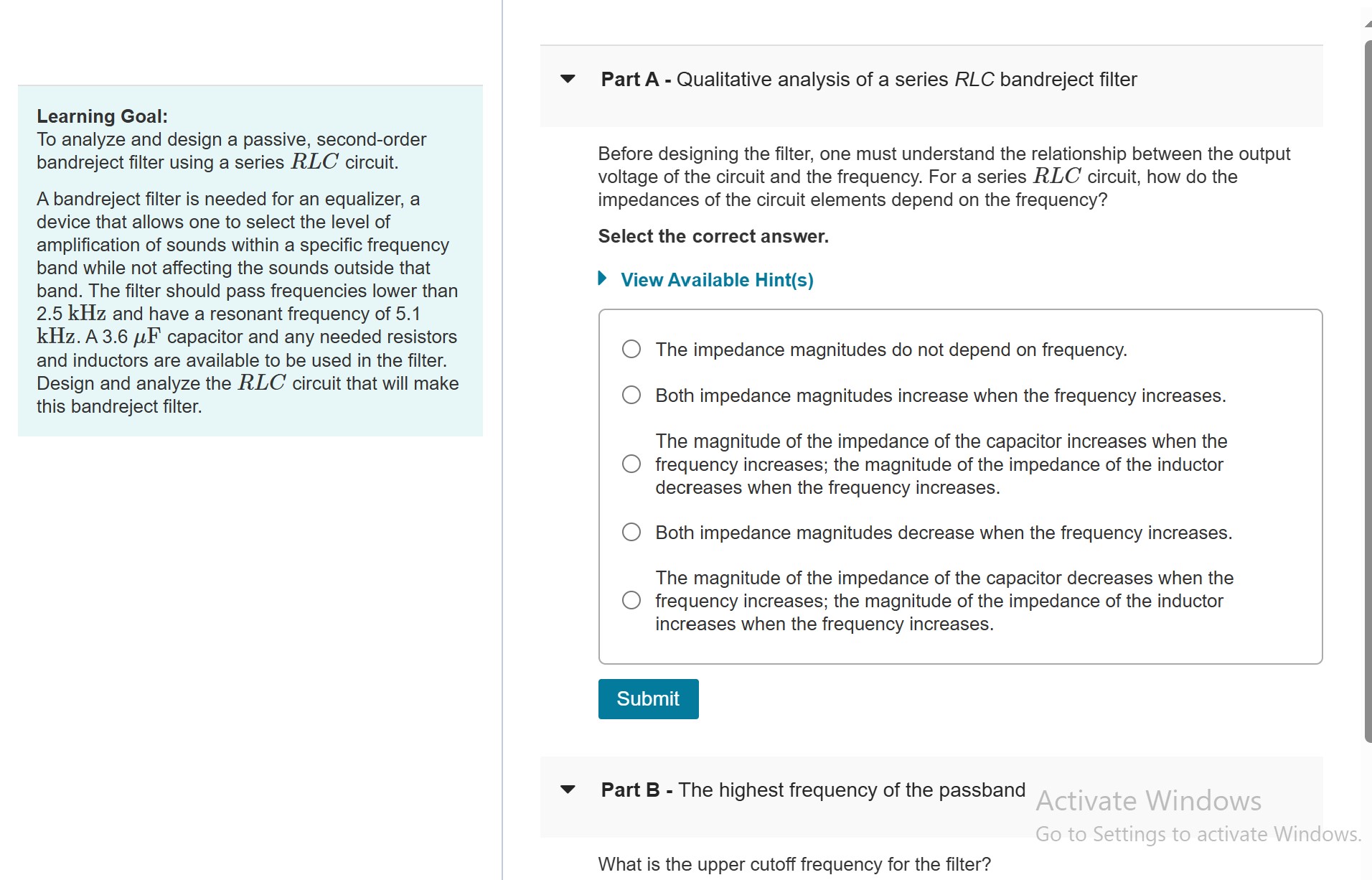
To analyze and design a passive, secondorder bandreject filter using a series R L C circuit.
A bandreject filter is needed for an equalizer, a device that allows one to select the level of amplification of sounds within a specific frequency band while not affecting the sounds outside that band. The filter should pass frequencies lower than kHz and have a resonant frequency of kHz A mu mathrm~F capacitor and any needed resistors and inductors are available to be used in the filter. Design and analyze the R L C circuit that will make this bandreject filter.
Part A Qualitative analysis of a series RLC bandreject filter
Before designing the filter, one must understand the relationship between the output voltage of the circuit and the frequency. For a series R L C circuit, how do the impedances of the circuit elements depend on the frequency?
Select the correct answer.
View Available Hints
The impedance magnitudes do not depend on frequency.
Both impedance magnitudes increase when the frequency increases.
The magnitude of the impedance of the capacitor increases when the frequency increases; the magnitude of the impedance of the inductor decreases when the frequency increases.
Both impedance magnitudes decrease when the frequency increases.
The magnitude of the impedance of the capacitor decreases when the frequency increases; the magnitude of the impedance of the inductor increases when the frequency increases.
Part B The highest frequency of the passband
Activate Windows
Go to Settings to activate Windows.
What is the upper cutoff frequency for the filter?
Step by Step Solution
There are 3 Steps involved in it
1 Expert Approved Answer
Step: 1 Unlock

Question Has Been Solved by an Expert!
Get step-by-step solutions from verified subject matter experts
Step: 2 Unlock
Step: 3 Unlock