

Question: Learning Objectives Objective 1 : Interpret information provided on a pump performance curve Objective 2 :Differentiate between NPSH R and NPSH A Objective 3 :
Learning Objectives
Objective : Interpret information provided on a pump performance curve
Objective :Differentiate between NPSH R and NPSH A
Objective : Explain the vapor pressure of a fluid
Objective : Calculate NPSH A
Problems
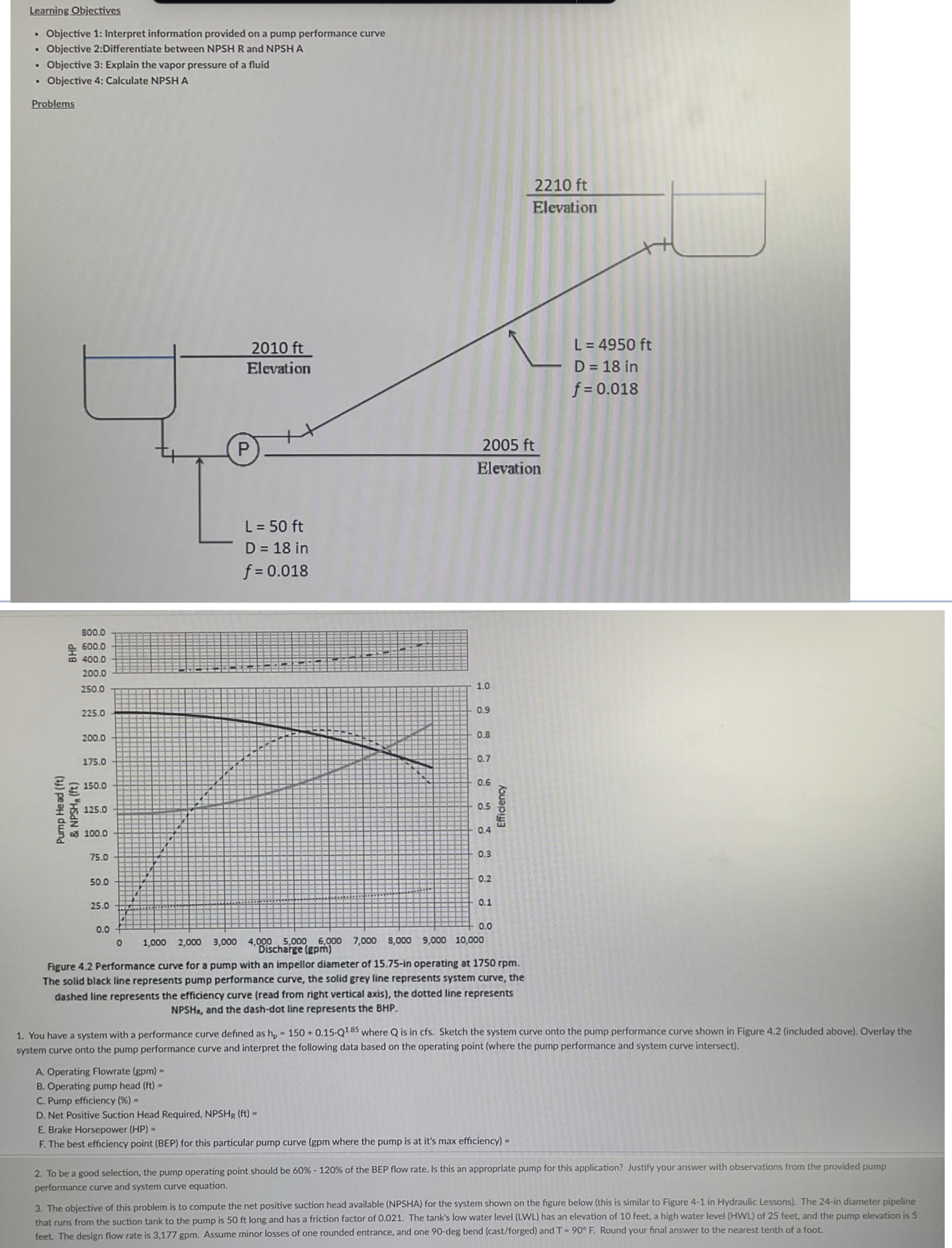
Figure Performance curve for a pump with an impellor diameter of in operating at rpm The solid black line represents pump performance curve, the solid grey line represents system curve, the dashed line represents the efficiency curve read from right vertical axis the dotted line represents NPSH and the dashdot line represents the BHP
You have a system with a performance curve defined as where is in cfs Sketch the system curve onto the pump performance curve shown in Figure included above Overlay the system curve onto the pump performance curve and interpret the following data based on the operating point where the pump performance and system curve intersect
A Operating Flowrate
B Operating pump head
C Pump efficiency
D Net Positive Suction Head Required,
E Brake Horsepower HP
F The best efficiency point BEP for this particular pump curve gpm where the pump is at it's max efficiency
To be a good selection, the pump operating point should be of the BEP flow rate. Is this an appropriate pump for this application? Justify your answer with observations from the provided pump performance curve and system curve equation.
The objective of this problem is to compute the net positive suction head available NPSHA for the system shown on the figure below this is similar to Figure in Hydraulic Lessons The in diameter pipeline that runs from the suction tank to the pump is ft long and has a friction factor of The tanks low water level has an elevation of feet, a high water level HWL of feet, and the pump elevation is feet. The design flow rate is Assume minor losses of one rounded entrance, and one deg bend castforged and Round your final answer to the nearest tenth of a foot.
Step by Step Solution
There are 3 Steps involved in it
1 Expert Approved Answer
Step: 1 Unlock

Question Has Been Solved by an Expert!
Get step-by-step solutions from verified subject matter experts
Step: 2 Unlock
Step: 3 Unlock