

Question: LOOK AT THE IMAGE AND ANSWER EVERY QUESTION ASKED. Divide a plain white sheet of paper into quarters, then sketch the simplest possible model of
LOOK AT THE IMAGE AND ANSWER EVERY QUESTION ASKED. Divide a plain white sheet of paper into quarters, then sketch the simplest possible model of a
screwdriver for each of the following uses:
ai Load analysis FBD Draw the applied forcestorques and label any model parameters.
Describe each model parameter in words or less. Upper left quadrant.
aii Firstorder stress analysis. Draw the simple model and describe it in words or less.
Upper right quadrant.
aiii More detailed stress analysis. Draw the simplest useful model and explain what type of
analysis tool you might use. Lower left quadrant.
aiv Contact stresses. Draw the simplest useful model you might use and provide a brief
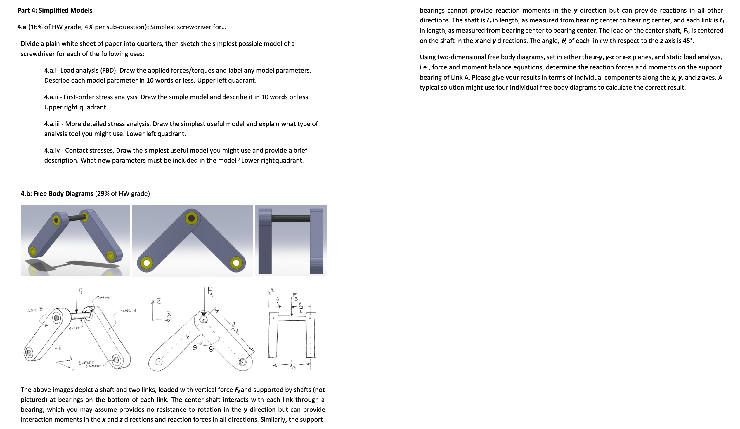
description. What new parameters must be included in the model? Lower right quadrant. The above images depict a shaft and two links, loaded with vertical force Fs and supported by shafts not
pictured at bearings on the bottom of each link. The center shaft interacts with each link through a
bearing, which you may assume provides no resistance to rotation in the y direction but can provide
interaction moments in the x and z directions and reaction forces in all directions. Similarly, the support
bearings cannot provide reaction moments in the y direction but can provide reactions in all other
directions. The shaft is Ls in length, as measured from bearing center to bearing center, and each link is Ll
in length, as measured from bearing center to bearing center. The load on the center shaft, Fs is centered
on the shaft in the x and y directions. The angle, of each link with respect to the z axis is deg
Using twodimensional free body diagrams, set in either the xy yz or zx planes, and static load analysis,
ie force and moment balance equations, determine the reaction forces and moments on the support
bearing of Link A Please give your results in terms of individual components along the x y and z axes. A
typical solution might use four individual free body diagrams to calculate the correct result.
Step by Step Solution
There are 3 Steps involved in it
1 Expert Approved Answer
Step: 1 Unlock

Question Has Been Solved by an Expert!
Get step-by-step solutions from verified subject matter experts
Step: 2 Unlock
Step: 3 Unlock