

Question: L-shaped bracket is supported by the wall as shown (gravity neglected). Forces in x and z direction are acting at point A. Force in y
L-shaped bracket is supported by the wall as shown (gravity neglected). Forces in x and z direction are acting at point A. Force in y direction is acting at point B. Cross-section is 0.2x0.2 m in size. Fx=1000 N, Fy=50000 N and Fz=1000 N.
a) Calculate normal and shear stress at point C (10 points)
b) Draw the directions of the normal and shear stress on an element at C with respect to the coordinate system (5 points)
c) Draw Mohr's circle for the state of stress at point C. Principal normal stresses need to be visible from the circle, as well as the points you used to construct the circle. Determine first and second principal (normal) stress using equations. (10 points)
d) Determine the yield stress of the ductile material used for the bracket, if safety factor is 2, according to maximum-shear-stress theory (5 points)
e) Same as in d), but use maximum-distortion-energy theory
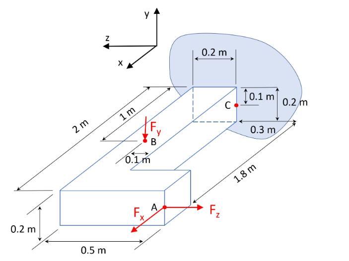
0.2 m 2 m Z 0.5 m 1m Y y B 0.1 m F. A 0.2 m LL N C 0.1 m 0.3 m 1.8 m 0.2 m
Step by Step Solution
There are 3 Steps involved in it
a To calculate the normal and shear stress at point C we need to consider the forces acting at points A and B Lets denote the coordinates of point C a... View full answer

Get step-by-step solutions from verified subject matter experts