

Question: MAIN PROGRAM * * * * * * * * * * * * * * * * * * * * * * *
MAIN PROGRAM
Port F has pins.
PFO Bit SW
PFl Bitl Red LED
PFBit Blue LED
PFBit Green LED
PFBit SW
Start
BL portFconfig
loop
B loop THUMB
; Base address for Port F Data Register
GPIOPORTFDATAR EQU xFC ; GPIO Data Register GPIODATA
; Test
redPattern
bluePattern
greenPattern
EQU
EQU
EQU
; Test
; redPattern
;bluePattern
EQU
; greenPattern
EQU
EQU
; Test
; redPattern
;bluePattern
EQU
; greenPattern
EQU
EQU
AREA
text CODE, READONLY, ALIGN
; Flash ROM
EXPORT Start
IMPORT portFconfigGPIO on the TMC: Sequencebased
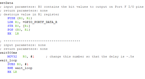
Output Colors: setData
; input parameters: RO contains the bit values to output on Port F IO pins
; return parameters: none
; destroys value in Rl register
PUSH RO RI
LDR RlGPIOPORTFDATAR
STR ROR
POP R R
BX LR
; input parameters: none
; return parameters: none
waitms
MOV R # ; change this number so that the delay is ~s
waitloop
SUBS RO #
BNE waitloop
BX LRThe general purpose is to familiarize you further with the software development steps
using the uVision simulator. You will learn how to perform digital inputoutput on parallel ports of the
TMC Software skills you will learn include shifting and rotation of registers.
You are NOT allowed to use conditional branches in your solution.
The ONLY instructions that you are allowed to use in your solution are:
Rotates
Shifts
Moves
Unconditional Branches including BL
You are also allowed to call the two subroutines provided setData & waitms No other
instructions or subroutines are allowed.
In addition, your program not including comments, directives, and subroutines must be lines
of code or less.
Instructions
Use the starter project provided to you. Submit the project folder to in ONE zip file and the lab report as
a separate PDF file.
Overview
The objective of this system is to make the LEDs on the LaunchPad blink in a very specific order. You will
be given some test patters to try out. Each test pattern has parts: the red pattern, blue pattern, and the
green pattern. The pattern begins in bit and ends in bit However, your program will repeat each
bit sequence indefinitely.
For instance, if the patterns were given as follows:
redPattern EQU
bluePattern EQU
greenPattern EQU
then the first action is that the LaunchPad would turn all LEDs RBG on for ms because bit of each
pattern is The second action is to turn the LEDs off for ms because bit of each pattern is low.
ECE
Microprocessor Systems
If the pattern were instead as follows:
redPattern EQU
bluePattern EQU
greenPattern EQU
then only the red LED would flash because the blue and green patterns are always
The last bits to be output are bits of each pattern. Then the whole sequence begins again. Note that
the patterns can be any combination of s and s for each color.
You will be using one of the IO ports on the TMcPort F PF Port F has bits that are hardwired
on LaunchPad to the LEDs. The outputs are in positive logic:
outputting a will turn on the LED,
outputting a will turn off the LED.
Below is the mapping of the IO pins on Port F that are hardwired to the LEDs.
Bit is an output connected to the Red LED
Bit is an output connected to the Blue LED
Bit is an output connected to the Green LED
You are given two subroutines in the starter project to use as needed:
setData This subroutine outputs the data bits to the microcontroller IO pins. You must
ensure that the value that you want to send to the red LED is in bit the value that you want to
send to the blue LED is in bit and the value that you want to send to the green LED is in bit
All other bit values will be ignored. The data to output to the LEDs must be in R when you call
the subroutine.
There is no return data. This subroutine overwrites the value in R
The subroutine is called as follows:
BL setData
waitms This subroutine should just provide ms of time delay. You must edit the first
instruction in the subroutine so that the delay time is approximately ms each time the
subroutine is called.
There is no return data. This subroutine overwrites the value in R
The subroutine is called as follows:
BL waitXms
Hello! I am confuse and dont understand. Can you show me the step and code? What do i write in main?
Step by Step Solution
There are 3 Steps involved in it
1 Expert Approved Answer
Step: 1 Unlock

Question Has Been Solved by an Expert!
Get step-by-step solutions from verified subject matter experts
Step: 2 Unlock
Step: 3 Unlock