

Question: Make a drawing(example mentioned below) that shows the clock cycle at which each of the instructions in the sequence given below would be completed, assuming
Make a drawing(example mentioned below) that shows the clock cycle at which each of the instructions in the sequence given below would be completed, assuming the 5-stage MIPS pipeline without forwarding discussed in class, and numbering the clock cycle at which the first of the instructions is fetched as clock cycle 1. You must examine and show the dependency for each instruction in the given sequence. Do not reorder the instructions. Instructions are fetched and executed exactly in the order given below, with the pipeline stalling if necessary. addi $s2, $s2, 1 add $s6, $s1, $s3 add $s1, $s2, $s3 lw $s5, 0($s1) lw $t1, 0($s5)
Example drawing
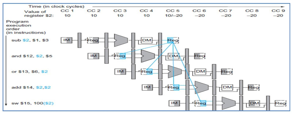
Time (in clock cycles) Value of register $2 CC 1 10 CC 2 10 CC 3 10 CC 4 10 CC 5 10/-2o CC 6 -20 CC 7 -20 CC 8 -20 CC 9 -20 Program execution order (in instructions) sub $2. $1. $3 IM and $12. $2, $5 IM eg or $13, $6. $2 IM DM add $14. S2,$2 IM sw $15. 100(S2) IM DM
Step by Step Solution
There are 3 Steps involved in it

Get step-by-step solutions from verified subject matter experts