

Manipulator (Fig. 8.3), which consists of the links 1, 2 and capture D is driven by...
Fantastic news! We've Found the answer you've been seeking!
Question:
Transcribed Image Text:
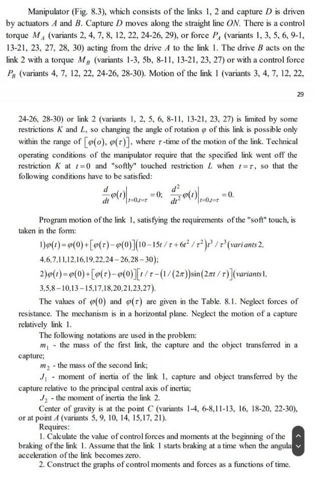
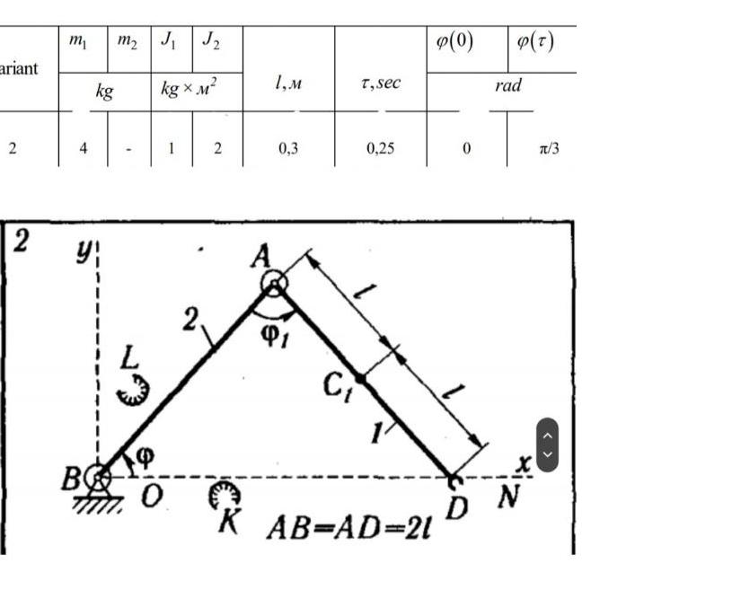
Manipulator (Fig. 8.3), which consists of the links 1, 2 and capture D is driven by actuators A and B. Capture D moves along the straight line ON. There is a control torque M (variants 2, 4, 7, 8, 12, 22, 24-26, 29), or force P, (variants 1, 3, 5, 6, 9-1, 13-21, 23, 27, 28, 30) acting from the drive A to the link 1. The drive B acts on the link 2 with a torque MB (variants 1-3, 5b, 8-11, 13-21, 23, 27) or with a control force P (variants 4, 7, 12, 22, 24-26, 28-30). Motion of the link 1 (variants 3, 4, 7, 12, 22, 24-26, 28-30) or link 2 (variants 1, 2, 5, 6, 8-11, 13-21, 23, 27) is limited by some restrictions K and L, so changing the angle of rotation of this link is possible only within the range of [po), p(r)], where r-time of the motion of the link. Technical operating conditions of the manipulator require that the specified link went off the restriction K at 1=0 and "softly" touched restriction L when t-r, so that the following conditions have to be satisfied: (1)-03-² = 0; t=0J=r 29 = 0. - the mass of the second link; Program motion of the link 1, satisfying the requirements of the "soft" touch, is taken in the form: 1)p(t)=p(0) +[p(z) - p(0)](10-15t/r+61²/t²)3³ / 7³ (variants 2, 4,6,7,11,12,16,19,22,24-26,28-30); 2)p(t)=P(0) +[p(t)-p(0)][t/t-(1/(2x)) sin(2rt / T)](variants 1, 3,5,8-10,13-15,17,18,20,21,23,27). The values of (0) and o(r) are given in the Table. 8.1. Neglect forces of resistance. The mechanism is in a horizontal plane. Neglect the motion of a capture relatively link 1. The following notations are used in the problem: m, the mass of the first link, the capture and the object transferred in a capture; m₂ J₁ moment of inertia of the link 1, capture and object transferred by the capture relative to the principal central axis of inertia; J₂ the moment of inertia the link 2. Center of gravity is at the point C (variants 1-4, 6-8,11-13, 16, 18-20, 22-30), or at point A (variants 5, 9, 10, 14, 15, 17, 21). Requires: 1. Calculate the value of control forces and moments at the beginning of the braking of the link 1. Assume that the link 1 starts braking at a time when the angula: ✓ acceleration of the link becomes zero. 2. Construct the graphs of control moments and forces as a functions of time. ariant 2 2 m₁ m₂ J₁ J₂ kg x M² kg 4T y B 0 2, 2 1,M 0,3 91 T, sec Ct 0,25 K AB=AD=21 p(0) (T) rad T DN T/3 Manipulator (Fig. 8.3), which consists of the links 1, 2 and capture D is driven by actuators A and B. Capture D moves along the straight line ON. There is a control torque M (variants 2, 4, 7, 8, 12, 22, 24-26, 29), or force P, (variants 1, 3, 5, 6, 9-1, 13-21, 23, 27, 28, 30) acting from the drive A to the link 1. The drive B acts on the link 2 with a torque MB (variants 1-3, 5b, 8-11, 13-21, 23, 27) or with a control force P (variants 4, 7, 12, 22, 24-26, 28-30). Motion of the link 1 (variants 3, 4, 7, 12, 22, 24-26, 28-30) or link 2 (variants 1, 2, 5, 6, 8-11, 13-21, 23, 27) is limited by some restrictions K and L, so changing the angle of rotation of this link is possible only within the range of [po), p(r)], where r-time of the motion of the link. Technical operating conditions of the manipulator require that the specified link went off the restriction K at 1=0 and "softly" touched restriction L when t-r, so that the following conditions have to be satisfied: (1)-03-² = 0; t=0J=r 29 = 0. - the mass of the second link; Program motion of the link 1, satisfying the requirements of the "soft" touch, is taken in the form: 1)p(t)=p(0) +[p(z) - p(0)](10-15t/r+61²/t²)3³ / 7³ (variants 2, 4,6,7,11,12,16,19,22,24-26,28-30); 2)p(t)=P(0) +[p(t)-p(0)][t/t-(1/(2x)) sin(2rt / T)](variants 1, 3,5,8-10,13-15,17,18,20,21,23,27). The values of (0) and o(r) are given in the Table. 8.1. Neglect forces of resistance. The mechanism is in a horizontal plane. Neglect the motion of a capture relatively link 1. The following notations are used in the problem: m, the mass of the first link, the capture and the object transferred in a capture; m₂ J₁ moment of inertia of the link 1, capture and object transferred by the capture relative to the principal central axis of inertia; J₂ the moment of inertia the link 2. Center of gravity is at the point C (variants 1-4, 6-8,11-13, 16, 18-20, 22-30), or at point A (variants 5, 9, 10, 14, 15, 17, 21). Requires: 1. Calculate the value of control forces and moments at the beginning of the braking of the link 1. Assume that the link 1 starts braking at a time when the angula: ✓ acceleration of the link becomes zero. 2. Construct the graphs of control moments and forces as a functions of time. ariant 2 2 m₁ m₂ J₁ J₂ kg x M² kg 4T y B 0 2, 2 1,M 0,3 91 T, sec Ct 0,25 K AB=AD=21 p(0) (T) rad T DN T/3
Expert Answer:

Related Book For 

Posted Date:
Students also viewed these mechanical engineering questions
-
A particle that moves along a straight line has velocity v(t) = t2 et meters per second after seconds. How far will it travel during the first seconds?
-
A particle that moves along a straight line has velocity v(t) = t2e-t meters per second after seconds. How far will it travel during the first seconds?
-
Suppose an object moves along a straight line with position f(t) at time t. Write an expression for the instantaneous velocity of the object at time t = a. How can you interpret this velocity in...
-
Both high-income and low-income employees are covered by cafeteria plans. Under such plans, all employees may select from a list of non-taxable fringe benefits or they may elect to receive cash in...
-
Would it be possible to calculate the cost of protein synthesis, including the cost of making mRNA and DNA?
-
Sigrid contributed $200 every month for nine years into an RRSP earning 4.3% compounded annually. She then converted the RRSP into an annuity that pays her monthly for 20 years. If the first payment...
-
Consider the wine quality of young red wines data in Table B.19. Regressor $x_{1}$ is an indicator variable. Perform a thorough analysis of these data. What conclusions do you draw from this...
-
Kelley Company has completed Octobers sales and purchases journals (Shown below). a. Total and post the journals to T accounts for the general ledger and the accounts receivable and accounts payable...
-
Kohn Corporation statement of income and retained earnings year ended December 31, 19x2: Net Sales Expenses Cost of Goods Sold Selling, General and Administrative Depreciation Interest Net Income...
-
A new edition of a very popular textbook will be published a year from now. The publisher currently has 1,000 copies on hand and is deciding whether to do another printing before the new edition...
-
1. Write a single program containing several methods that will compute the sum of the first n terms of the series in the specific manners outlined below. (Let n = 100,000 to start and if you have...
-
The solid steel shaft AB (diameter 19mm) and CD (diameter 25mm) are connected by gears. For each shaft following material properties are valid" G = 77 GPa and Tmax = 55MPa. Both shafts are mounted...
-
10. Two positive charges, one 4.7 nC and the other 26 nC, are placed a fixed distance 2.65 cm apart. At what positions could we place a third charge so that it would remain stationary under the...
-
A block is hanging vertically from a spring at the equilibrium displace- ment. The block is then pulled down a bit and released from rest. Draw the free-body diagram for the block in each of the...
-
Find the coefficient A by normalizing the wave function Y = A (1-21) 2
-
For the circuit shown, the voltmeter (V) reads 5.0 V and the ammeter (A) reads 5.4 mA. What is the emf of the battery ? V w A R A. 32.0 V B. 21.2 V C. 16.2 V D. 11.2 V E. 22.0 V + w 3.00
-
F=810N As shown in the figure below, the truss is loaded by the force F in kN at the joint A. Answer the following questions: 1) Determine the internal forces of all truss members except CD 2) From...
-
Solve for the equilibria of the following discrete-time dynamical systems Pr pt+1 = Pr+2.0(I-Pr)
-
Let A be the area under the graph of an increasing continuous function f from a to b, and let Ln and Rn be the approximations to A with n subintervals using left and right endpoints, respectively....
-
Compute Îy and dy for the given values of x and dx = Îx. Then sketch a diagram like Figure 5 showing the line segments with lengths dx, dy, and Îy. (a) y = 2x - x2, x = 2 Îx =...
-
Find the area of the shaded region. (a) (b) 4 + 3 sin
-
Give some examples of models in which the dependent variable is a count variable.
-
Explain why estimation of a supply and demand model requires an alternative to ordinary least squares (OLS).
-
Describe what is meant by the phrase "sample selection."

Study smarter with the SolutionInn App