

Question: Material Yield Strength (MPa) 300 Tensile Strength (MPa) 430 Modulus of Elasticity (GPa) 75 Poisson's Ratio Aluminium 6061-T6 0.33 4140 Steel 525 800 210 0.3
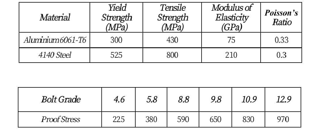
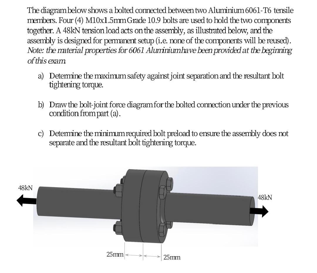
Material Yield Strength (MPa) 300 Tensile Strength (MPa) 430 Modulus of Elasticity (GPa) 75 Poisson's Ratio Aluminium 6061-T6 0.33 4140 Steel 525 800 210 0.3 Bolt Grade 4.6 5.8 8.8 9.8 10.9 12.9 Proof Stress 225 380 590 650 830 970 The diagram below shows a bolted connected between two Aluminium 6061-T6 tensile members. Four (4) M10x1.5mm Grade 10.9 bolts are used to hold the two components together. A 48kN tension load acts on the assembly, as illustrated below, and the assembly is designed for permanent setup (i.e. none of the components will be reused). Note: the material properties for 6061 Aluminiumhave been provided at the beginning of this exam a) Determine the maximum safety against joint separation and the resultant bolt tightening torque. b) Draw the bolt-joint force diagram for the bolted connection under the previous condition from part (a). c) Determine the minimum required bolt preload to ensure the assembly does not separate and the resultant bolt tightening torque. 48kN 48kN 25mm 25mm Material Yield Strength (MPa) 300 Tensile Strength (MPa) 430 Modulus of Elasticity (GPa) 75 Poisson's Ratio Aluminium 6061-T6 0.33 4140 Steel 525 800 210 0.3 Bolt Grade 4.6 5.8 8.8 9.8 10.9 12.9 Proof Stress 225 380 590 650 830 970 The diagram below shows a bolted connected between two Aluminium 6061-T6 tensile members. Four (4) M10x1.5mm Grade 10.9 bolts are used to hold the two components together. A 48kN tension load acts on the assembly, as illustrated below, and the assembly is designed for permanent setup (i.e. none of the components will be reused). Note: the material properties for 6061 Aluminiumhave been provided at the beginning of this exam a) Determine the maximum safety against joint separation and the resultant bolt tightening torque. b) Draw the bolt-joint force diagram for the bolted connection under the previous condition from part (a). c) Determine the minimum required bolt preload to ensure the assembly does not separate and the resultant bolt tightening torque. 48kN 48kN 25mm 25mm
Step by Step Solution
There are 3 Steps involved in it

Get step-by-step solutions from verified subject matter experts