

Question: MATLAB Input of the system is the voltage source V applied to the motor's armature, while the output is the angular displacement of the shaft
MATLAB
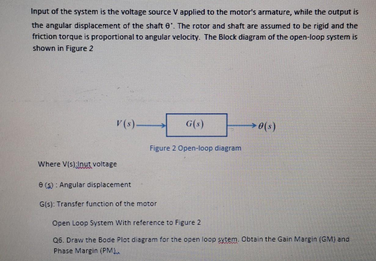
Input of the system is the voltage source V applied to the motor's armature, while the output is the angular displacement of the shaft O'. The rotor and shaft are assumed to be rigid and the friction torque is proportional to angular velocity. The Block diagram of the open-loop system is shown in Figure 2 V(s) G(s) 0(s) Figure 2 Open-loop diagram Where V(s):Inut voltage 09: Angular displacement Gis): Transfer function of the motor Open Loop System With reference to Figure 2 06. Draw the Bode Plot diagram for the open loop sytem. Obtain the Gain Margin (GM) and Phase Margin (PM. Input of the system is the voltage source V applied to the motor's armature, while the output is the angular displacement of the shaft O'. The rotor and shaft are assumed to be rigid and the friction torque is proportional to angular velocity. The Block diagram of the open-loop system is shown in Figure 2 V(s) G(s) 0(s) Figure 2 Open-loop diagram Where V(s):Inut voltage 09: Angular displacement Gis): Transfer function of the motor Open Loop System With reference to Figure 2 06. Draw the Bode Plot diagram for the open loop sytem. Obtain the Gain Margin (GM) and Phase Margin (PM
Step by Step Solution
There are 3 Steps involved in it

Get step-by-step solutions from verified subject matter experts