

Question: Matlab. Just fill in this code provided below. clear; close; clc; format short g; %% Section 1: Define all variables with the data for this
Matlab.
Just fill in this code provided below.
clear; close; clc; format short g;
%% Section 1: Define all variables with the data for this system.
% Equate the variables below to their descriptions
NN = 3; %NN is the Total no of nodes in the truss
Nelem = 2; %Nelem Total no of elements in the truss
% Fill the Elcon matrix that contains the nodal values at the end of each element
Elcon = [];
% Fill the Coord matrix with the x and y distances of each of the nodes
Coord = [];
% Define the number of DOF that each node can have (This is only a 2D problem)
NdofN = ;
Ndof = NN*NdofN;
% Fill the area vector with the Cross sec Area of each of the elements
Area = [];
% Fill Emod vector with the Young's Modulus of each of the elements
Emod = [];
% Boundary conditions
Icon = zeros(Ndof,2);
% Fill the elements of the first column of Icon Matrix with node constraint information (1=constrained,0=Not constrained)
%Icon = [_,_ 1st element (constrained Y/N, force applied to node)
% 0,10 2nd element (constrained N, force=10)
% 1,0 3rd element (constrained Y, force=0)
% _,_]; ect.
% Use matrix indexing to fill the Icon matrix using the logic presented
% above and information from the assignment.
Icon(i,1) = ;
% Fill the elements of the Second column of Icon contains information on
% loads applied to each node. (same logic as above)
Icon(i,2) = ;
%% Segment-2: Assembling system stiffness matrix
% Build the system stiffness matrix by looping through each element
% Computing the element stiffness matrix and assembling it into the system stiffness matrix.
Ksys=zeros(Ndof,Ndof); %Initializing the system matrix
for Ielem=1:Nelem
Node1 = Elcon(Ielem,1); %Retrieving the first node of the element
Node2 = Elcon(Ielem,2); %Retrieving the second node of the element
length = memlength(Coord(Node1,1),Coord(Node1,2),Coord(Node2,1),Coord(Node2,2)); % calculate length of truss members from the coordinate
lam = lam_calc(Coord(Node1,1),Coord(Node1,2),Coord(Node2,1),Coord(Node2,2)); % calculate rotation matrix from the coordinate
Kelem = stiffness(Area(Ielem),Emod(Ielem),length,lam); % generate elememt stiffness matrix from area, modulus, length, and rotation matrix
% Assemble element matrix into global matrix
end
disp(Ksys)
%% Segment-3: Implementing boundary conditions
% Boundary conditions will be imposed to truss problem using constrain equation method
% copying load vector from 2nd colum of Icon to Fsys
Fsys = Icon(:,2);
% loop through all dofs to check constrain and update stiffness matrix
for i = 1:Ndof % check if dof is constrained using if statement, % Note: first column of Icon saved the constrain flag
if % put your logical expression here
Ksys ; % zero out the row
delta = ; % save corresponding constrain value from Icon to variable delta
if delta ~= 0 % check if delta is nonzero and subtract Ksys(:,i)*delta from Fsys
Fsys = Fsys - Ksys(:,i)*delta;
end
Ksys ; % zero out rest of the column
Ksys ; % set the diagonal element of the Ksys as 1 (don't use diag function)
Fsys ; % set force vector element as delta
end
end
disp(Ksys)
%% Segment-4: Obtaining displacement solution
% find displacement of the nodes, dsys, from Ksys and Fsys
dsys = ;
%% Segment-5: Post processing of solution
Strain = zeros(Nelem,1); %Initializing strain vector
Stress = zeros(Nelem,1); %Initializing stress vector
Reac = zeros(Ndof,1); %Initializing reaction force vector
% looping through all elements to calculate nodal force and element stress
for Ielem = 1:Nelem
Node1 = ; %retrieve first node from element connection
Node2 = ; %retrieve second node from element connection
NN1 = ; %define the nodal address variable
NN2 = ; %define the nodal address variable
uglob = zeros(4,1); %initializing global displacement vector
uglob(1) = dsys(); %retrieve global x-displacement of node-1 of element-i
uglob(2) = dsys(); %retrieve global y-displacement of node-1 of element-i
uglob(3) = dsys(); %retrieve global x-displacement of node-2 of element-i
uglob(4) = dsys(); %retrieve global y-displacement of node-2 of element-i
% Calculate length of the member using memlength function
% Calculate rotation matrix of the member using lam_calc function
% Calculate extended transformation matrix, T, from rotation matrix
% Check stiffness function to learn the operation
% transform global displacement to local displacement using T
uloc = ;
% calculate element strain using length and displacement vector
Strain(Ielem) = ;
% calculate element stress from strain using Hooke's law
Stress(Ielem) = ;
% Calculate force from stress (multiply it by area)
Froce = ;
% Extended the local force vector using equilibrium condition
Floc = ;
% transform the local force vector to global force vector using T'
Fglob = ;
% Add global force from each element to obtain reaction force
Reac(NN1) = Reac(NN1)+Fglob(1);
Reac(NN1+1) = Reac(NN1+1)+Fglob(2);
Reac(NN2) = Reac(NN2)+Fglob(3);
Reac(NN2+1) = Reac(NN2+1)+Fglob(4);
end
disp(Stress) % prints element stress
disp(Reac) % prints nodal reaction force
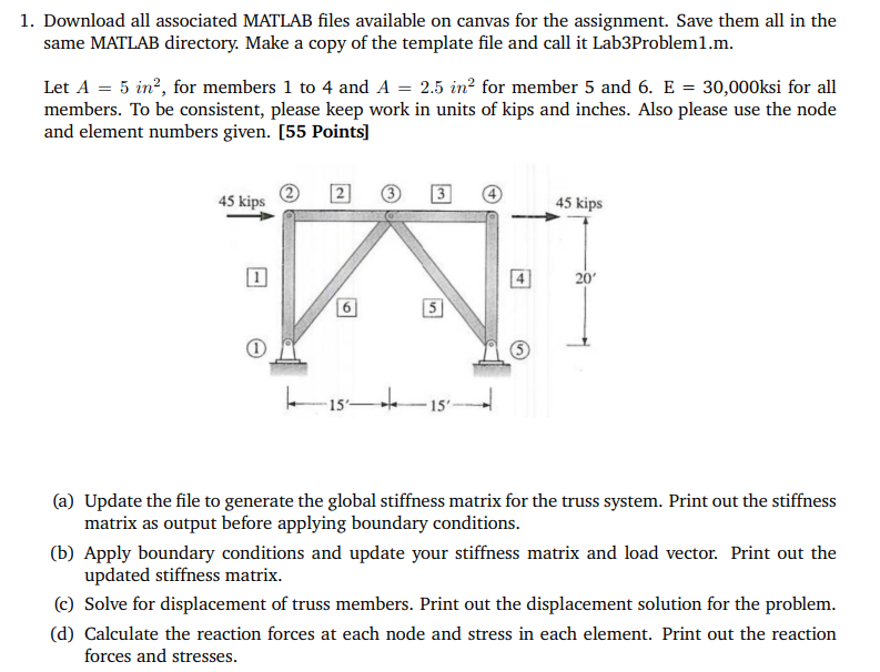
1. Download all associated MATLAB files available on canvas for the assignment. Save them all in the same MATLAB directory. Make a copy of the template file and call it Lab3Problem1.m. Let A=5in2, for members 1 to 4 and A=2.5in2 for member 5 and 6.E=30,000ksi for all members. To be consistent, please keep work in units of kips and inches. Also please use the node and element numbers given. [55 Points] (a) Update the file to generate the global stiffness matrix for the truss system. Print out the stiffness matrix as output before applying boundary conditions. (b) Apply boundary conditions and update your stiffness matrix and load vector. Print out the updated stiffness matrix. (c) Solve for displacement of truss members. Print out the displacement solution for the problem. (d) Calculate the reaction forces at each node and stress in each element. Print out the reaction forces and stresses
Step by Step Solution
There are 3 Steps involved in it

Get step-by-step solutions from verified subject matter experts