

Question: Measuring the Time to Convert Ardunio Write a program to measure the ADC conversion time. Configure pin PB0 to be an output pin. Write a
 Measuring the Time to Convert Ardunio
Write a program to measure the ADC conversion time. Configure pin PB0 to be an output pin. Write a one to PB0, then start an ADC conversion and write a 0 to PB0 after the conversion is complete. Measure the conversion time using an oscilloscope (or Logic Pirate) (Hint: Do not write to the serial port with this program because it can alter your measured conversion time).
how to write the code?
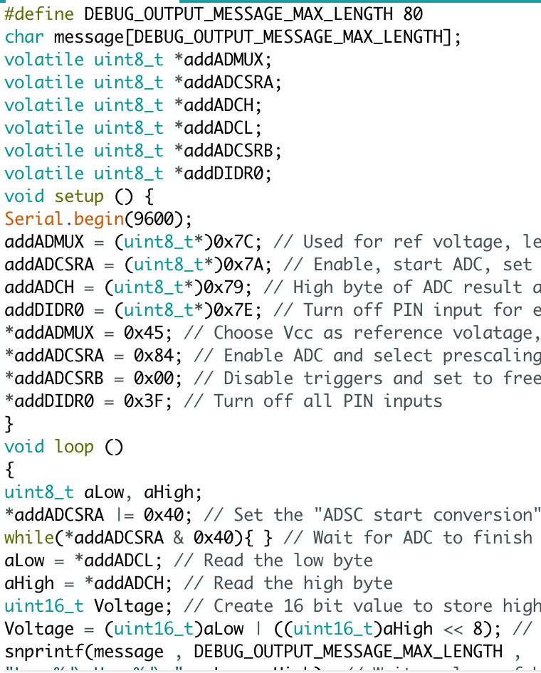
#define DEBUG OUTPUT MESSAGE MAX LENGTH 80 char message DEBUG OUTPUT MESSAGE MAX LENGTH; volatile uint8 t addADMUX volatile uint8_t addADCSRA volatile uint8 t addADCH volatile uint8 t addADCL volatile uint8 t addADC SRB volatile uint8 t add DTDRO void setup CD 1 Serial begin 9600); addADMUX uint8 t* 00x7C; Used for ref voltage, le addADCSRA uint8 t* 00x7A Enable start ADC, set addADCH uint8 t* 00x79 High byte of ADC result a addDIDRO uint8 t* Turn off PIN input for e addADMUX 0x45 Choose Vecc as reference volatage addADCSRA 10x84; Enable ADC and select prescaling addADC SRB 0x00 Disable triggers and set to free add DTDRO 0x3F Turn off all PIN inputs void loop O uint8 t Low aHigh addADCSRA I 0x40 Set the "ADSC start conversion while CaddADCSRA & 0x4001 Wait for ADC to finish aLow addADCL Read the low byte High addADCH Read the high byte a uint16 t Voltage Create 16 bit value to store high Voltage uint16 t a uint16 t Da High 8); Low snprintf message DE BUG OUTPUT MESSAGE MAX LENGTH
Step by Step Solution
There are 3 Steps involved in it

Get step-by-step solutions from verified subject matter experts