

Question: MME 2 4 1 - Statics Design Problem 1 - Car Jack Design and Analysis Overview: The standard scissors jack provides an excellent example of
MME Statics
Design Problem Car Jack Design and Analysis
Overview: The standard "scissors jack" provides an excellent example of a trussstyle system. All members in the jack are force members, and all connections are accurately modeled as pin joints.
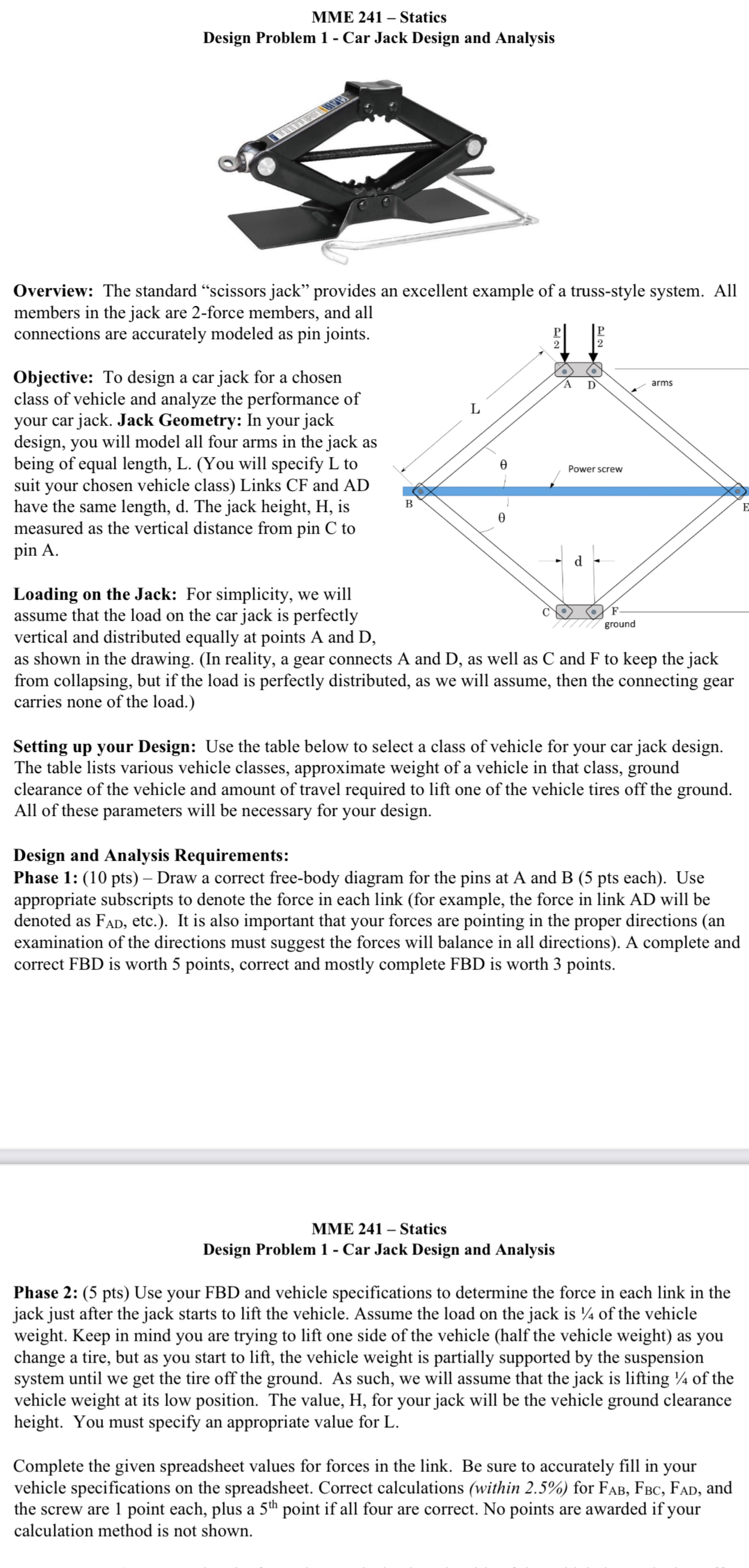
Objective: To design a car jack for a chosen class of vehicle and analyze the performance of your car jack. Jack Geometry: In your jack design, you will model all four arms in the jack as being of equal length, LYou will specify to suit your chosen vehicle class Links CF and AD have the same length, The jack height, is measured as the vertical distance from pin C to pin A
Loading on the Jack: For simplicity, we will assume that the load on the car jack is perfectly vertical and distributed equally at points A and D as shown in the drawing. In reality, a gear connects A and D as well as C and F to keep the jack from collapsing, but if the load is perfectly distributed, as we will assume, then the connecting gear carries none of the load.
Setting up your Design: Use the table below to select a class of vehicle for your car jack design. The table lists various vehicle classes, approximate weight of a vehicle in that class, ground clearance of the vehicle and amount of travel required to lift one of the vehicle tires off the ground. All of these parameters will be necessary for your design.
Design and Analysis Requirements:
Phase : pts Draw a correct freebody diagram for the pins at A and B pts each Use appropriate subscripts to denote the force in each link for example, the force in link AD will be denoted as etc. It is also important that your forces are pointing in the proper directions an examination of the directions must suggest the forces will balance in all directions A complete and correct FBD is worth points, correct and mostly complete FBD is worth points.
MME Statics
Design Problem Car Jack Design and Analysis
Phase : pts Use your FBD and vehicle specifications to determine the force in each link in the jack just after the jack starts to lift the vehicle. Assume the load on the jack is of the vehicle weight. Keep in mind you are trying to lift one side of the vehicle half the vehicle weight as you change a tire, but as you start to lift, the vehicle weight is partially supported by the suspension system until we get the tire off the ground. As such, we will assume that the jack is lifting of the vehicle weight at its low position. The value, H for your jack will be the vehicle ground clearance height. You must specify an appropriate value for L
Complete the given spreadsheet values for forces in the link. Be sure to accurately fill in your vehicle specifications on the spreadsheet. Correct calculations within for and the screw are point each, plus a point if all four are correct. No points are awarded if your calculation method is not shown.
Step by Step Solution
There are 3 Steps involved in it
1 Expert Approved Answer
Step: 1 Unlock

Question Has Been Solved by an Expert!
Get step-by-step solutions from verified subject matter experts
Step: 2 Unlock
Step: 3 Unlock