

Question: Model a 0000111 detector Moore Finite State Machine. PROCEDURE: First reference and understand the implementation of the 110 detector discussed in class. The Verilog
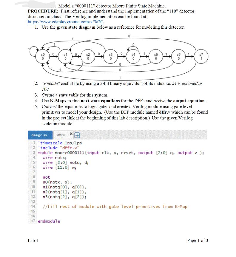
Model a "0000111" detector Moore Finite State Machine. PROCEDURE: First reference and understand the implementation of the "110" detector discussed in class. The Verilog implementation can be found at: https://www.cdaplayground.com/x/3a2C 1. Use the given state diagram below as a reference for modeling this detector. 0 OS Lab 1 0 wire notx; wire [2:0] notq, d; wire [11:0] w; 9 10 11 12 13 14 15 16 17 endmodule 0 0 1 2. "Encode" each state by using a 3-bit binary equivalent of its index i.e. s4 is encoded as 100 3. Create a state table for this system. 5. 4. Use K-Maps to find next state equations for the DFFs and derive the output equation. Convert the equations to logic gates and create a Verilog module using gate level primitives to model your design. (Use the DFF module named dffr.v which can be found in the project link at the beginning of this lab description.) Use the given Verilog skeleton module: 80 design.sv dffr.v 1 timescale 1ns/1ps 2 include "dffr.v" 3 module moore0000111(input clk, x, reset, output [2:0] q, output z ); 5 1 not no (notx, x), n1 (notq[0], q[0]), n2 (notq[1], q[1]), n3 (notq[2], q[2]); //fill rest of module with gate level primitives from K-Map Page 1 of 3
Step by Step Solution
There are 3 Steps involved in it

Get step-by-step solutions from verified subject matter experts