

Question: Module 1 1 Centering Block Build the following part parametrically in Solidwork. Parts shall be built from fully defined sketches using a combination of the
Module Centering Block
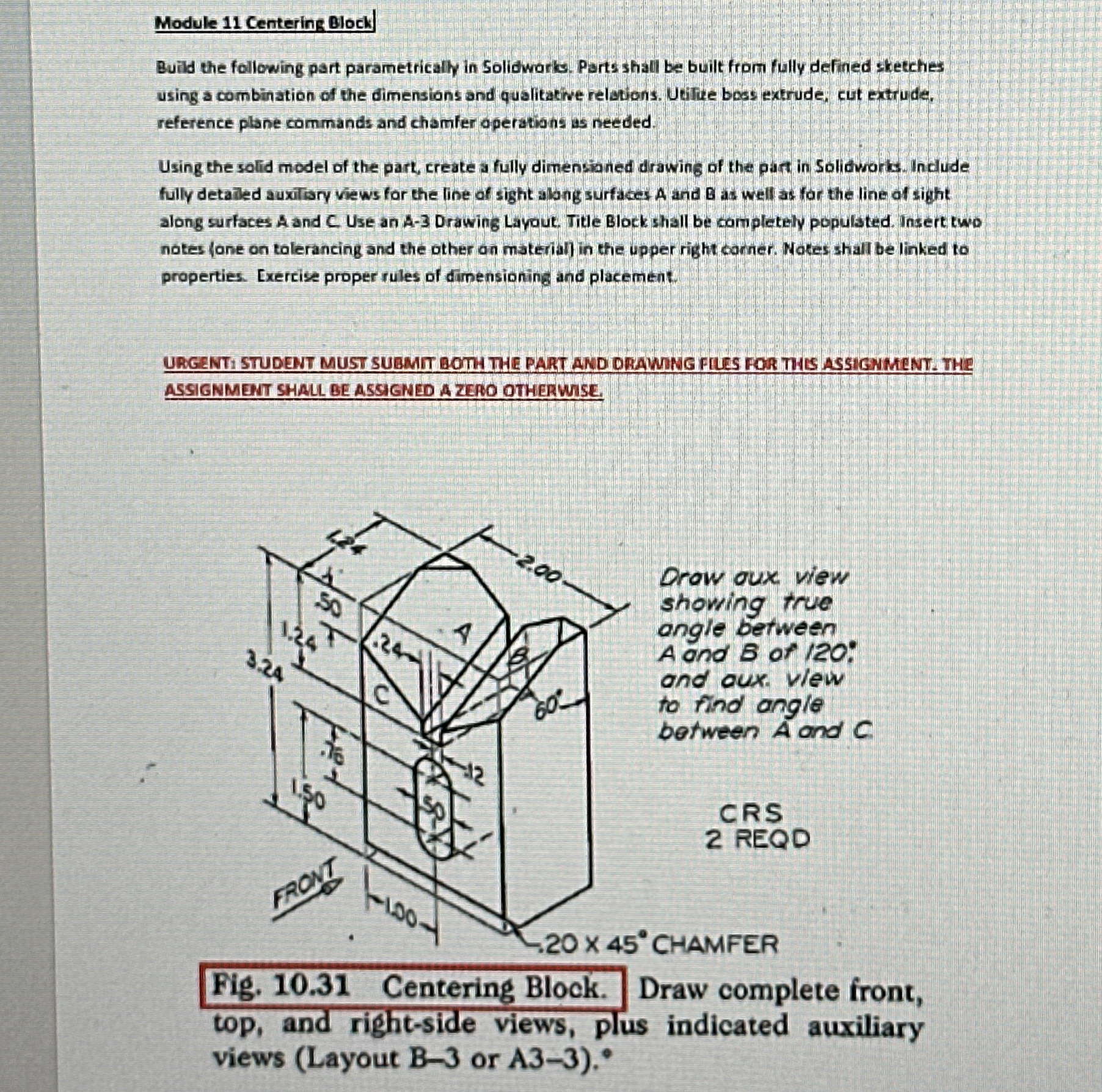
Build the following part parametrically in Solidwork. Parts shall be built from fully defined sketches using a combination of the dimensions and qualitative relations. Utifie boss extrude, cut extrude, reference plane commands and chamfer operations as needed.
Using the solid model of the part, create a fully dimensianed drawing of the part in Solidvorks. Include. fully detailed auxitiary views for the line of sight along surfaces A and B as well as for the line of sight along surfaces A and C Use an A Drawing Layout. Title Block shall be completely populated. Insert two notes ane on tolerancing and the other on materia in the upper right corner. Notes shall be linked to properties. Exercise proper rules of dimensioning and placement.
URGENTI STUDENT MUST SUBMIT BOTH THE PART AND DRAWING FIUES FOR THE ASSIGNMENT. THE ASSIGNMENT SHALL BE ASSIGNED A ZERIO OTHERWISE.
Drow oux view
showing true
angle between
A and of :
and aux. vlew
to find angle
between A and
CRS
REQD
'CHAMFER
Fig. Centering Block. Draw complete front, top, and rightside views, plus indicated auxiliary views Layout or
Step by Step Solution
There are 3 Steps involved in it
1 Expert Approved Answer
Step: 1 Unlock

Question Has Been Solved by an Expert!
Get step-by-step solutions from verified subject matter experts
Step: 2 Unlock
Step: 3 Unlock