

Question: module commutator( input hallGrn,hallYlw,hallBlu, // hall effect sensor inputs output [1:0] selGrn,selYlw,selBlu // determine FET drive combination ); ////////////////////////////////////////// // Declare any needed internal signals
![module commutator( input hallGrn,hallYlw,hallBlu, // hall effect sensor inputs output [1:0]](https://dsd5zvtm8ll6.cloudfront.net/si.experts.images/questions/2024/09/66fa474a56a53_28166fa4749c101c.jpg)
module commutator( input hallGrn,hallYlw,hallBlu, // hall effect sensor inputs output [1:0] selGrn,selYlw,selBlu // determine FET drive combination );
////////////////////////////////////////// // Declare any needed internal signals // // (for instance: rotation_state // ///////////////////////////////////////
////////////////////////////////////////////////\\ // sel states have 1 of 3 states: \\ // 0X => both FETs off (HIGH_Z) \\ // 10 => ~PWM to high FET and PWM to low FET \\ // 11 -> PWM to high FET and ~PWM to low FET \\ // Make use of these localparams to the comparisons // // in your nested ternary statement more readable // //////////////////////////////////////////////////// localparam HIGH_Z = 2'b0x; localparam LOW_PWM = 2'b10; localparam HIGH_PWM = 2'b11; ////////////////////////////////////////////// // Form a 3-bit rotation_state from: // // {hallGrn,hallYlw,hallBlu} concatenated // /////////////////////////////////////////// assign rotation_state = {hallGrn,hallYlw,hallBlu}; ///////////////////////////////////////////////// // form sel[1:0] signals using rotation state // // (Use a nested ternary statement for each // // of: selGrn, selYlw, selBlu) // /////////////////////////////////////////////
endmodule
Please complete the code above.
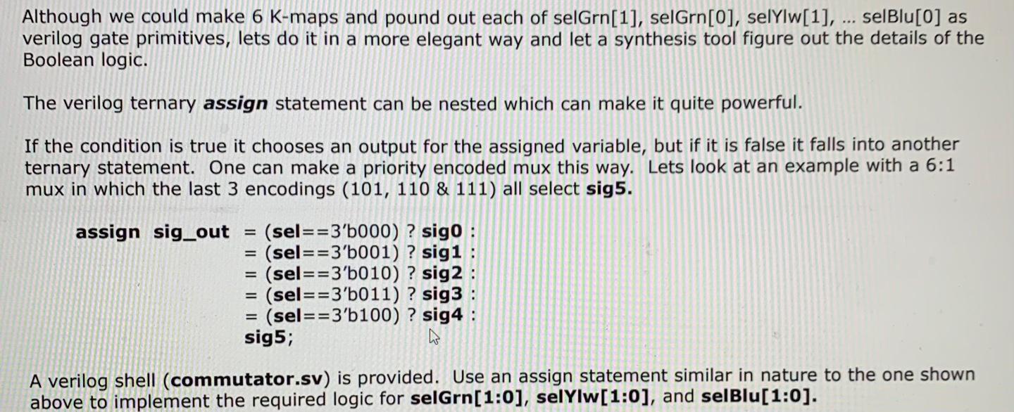
commutator.sv The basic job of the commutator is to choose the coil pairs that are driven and the direction current is driven through them based on the current position of the rotor. The current position of the rotor is determined by the hall effect sensor signals (hallGrn, hallelw, hallBlu). One can form a state vector by concantenating all three hall effect sensor signals. rotation_state {hallGrn, hallYlw,hallBlu} The coils are driven one of three ways: 1) Not driven: both FETs off (zero to both) (HIGH_Z) 2) Reverse current: ~PWM driven to high FET and PWM driven to low FET (LOW_PWM) 3) Forward current: PWM driven to high FETand ~PWM driven to low FET (HIGH_PWM) The following table shows the relationship between rotation_state as defined and the desired drive of the coils. rotation_state Green Coil (selGrn) Yellow Coil (selYlw) Blue Coil (selBlu) 3'b010 LOW PWM HIGH PWM HIGH Z 3'b011 LOW PWM HIGH Z HIGH PWM 3'b001 HIGH Z LOW PWM HIGH PWM 3'b101 HIGH PWM LOW_PWM HIGH Z 3'b100 HIGH PWM HIGH Z LOW PWM 3'b110 HIGH_Z HIGH_PWM LOW PWM For any combination not shown (3'b000 & 3'b111) all coils should be not driven (HIGH_Z). Although we could make 6 K-maps and pound out each of selGrn[1], selGrn[0], selYlw[1], ... selBlu[0] as verilog gate primitives, lets do it in a more elegant way and let a synthesis tool figure out the details of the Boolean logic. The verilog ternary assign statement can be nested which can make it quite powerful. If the condition is true it chooses an output for the assigned variable, but if it is false it falls into another ternary statement. One can make a priority encoded mux this way. Lets look at an example with a 6:1 mux in which the last 3 encodings (101, 110 & 111) all select sig5. assign sig_out = (sel==3'b000) ? sigo : - (sel==3'b001) ? sig1 = (sel==3'b010) ? sig2 : = (sel==3'b011) ? sig3 : - (sel==3'b100) ? sig4 : sig5; W A verilog shell (commutator.sv) is provided. Use an assign statement similar in nature to the one shown above to implement the required logic for selGrn[1:0], selylw[1:0], and selBlu[1:0]. commutator.sv The basic job of the commutator is to choose the coil pairs that are driven and the direction current is driven through them based on the current position of the rotor. The current position of the rotor is determined by the hall effect sensor signals (hallGrn, hallelw, hallBlu). One can form a state vector by concantenating all three hall effect sensor signals. rotation_state {hallGrn, hallYlw,hallBlu} The coils are driven one of three ways: 1) Not driven: both FETs off (zero to both) (HIGH_Z) 2) Reverse current: ~PWM driven to high FET and PWM driven to low FET (LOW_PWM) 3) Forward current: PWM driven to high FETand ~PWM driven to low FET (HIGH_PWM) The following table shows the relationship between rotation_state as defined and the desired drive of the coils. rotation_state Green Coil (selGrn) Yellow Coil (selYlw) Blue Coil (selBlu) 3'b010 LOW PWM HIGH PWM HIGH Z 3'b011 LOW PWM HIGH Z HIGH PWM 3'b001 HIGH Z LOW PWM HIGH PWM 3'b101 HIGH PWM LOW_PWM HIGH Z 3'b100 HIGH PWM HIGH Z LOW PWM 3'b110 HIGH_Z HIGH_PWM LOW PWM For any combination not shown (3'b000 & 3'b111) all coils should be not driven (HIGH_Z). Although we could make 6 K-maps and pound out each of selGrn[1], selGrn[0], selYlw[1], ... selBlu[0] as verilog gate primitives, lets do it in a more elegant way and let a synthesis tool figure out the details of the Boolean logic. The verilog ternary assign statement can be nested which can make it quite powerful. If the condition is true it chooses an output for the assigned variable, but if it is false it falls into another ternary statement. One can make a priority encoded mux this way. Lets look at an example with a 6:1 mux in which the last 3 encodings (101, 110 & 111) all select sig5. assign sig_out = (sel==3'b000) ? sigo : - (sel==3'b001) ? sig1 = (sel==3'b010) ? sig2 : = (sel==3'b011) ? sig3 : - (sel==3'b100) ? sig4 : sig5; W A verilog shell (commutator.sv) is provided. Use an assign statement similar in nature to the one shown above to implement the required logic for selGrn[1:0], selylw[1:0], and selBlu[1:0]
Step by Step Solution
There are 3 Steps involved in it

Get step-by-step solutions from verified subject matter experts