

Question: multivariable systems Consider the following two-input-two-output LTI system: [2 0,- (u+d) 0 -2*10* where U ER is the control input vector and deR represents the
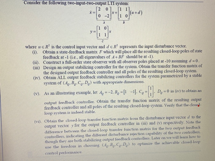
Consider the following two-input-two-output LTI system: [2 0,- (u+d) 0 -2*10* where U ER is the control input vector and deR represents the input disturbance vector. (i). Obtain a state-feedback matrix F which will place all the resulting closed-loop poles of state feedback at -1 (i.e., all eigenvalues of A+ BF should be at -1). (11). Construct a full-order state observer with all observer poles placed at -10 assuming d=0 (111) Design an output stabilizing controller for the system. Obtain the transfer function matrix of the designed output feedback controller and all poles of the resulting closed-loop system. (iv). Obtain ALL output feedback stabilizing controllers for the system parametrized by a stable system of (4.,B,C,D) with appropriate dimensions. (v). As an illustrating example, let 4 =-2. B = [1 -1]. Co=1. D. =0 in (iv) to obtain an output feedback controller. Obtain the transfer function matrix of the resulting output feedback controller and all poles of the resulting closed-loop system. Verify that the closed- loop system is indeed stable. (vi). Obtain the closed-loop transfer function matrix from the disturbance input vector d to the output vector for the output feedback controller in (11) and (v) respectively. Note the difference between the closed-loop transfer function matrix for the two output feedback controllers, indicating the different disturbance rejection capability of the two controllers though they are both stabilizing output feedback controllers. Later on we will learn how to use the freedom in choosing (49.B.C.D.) to optimize the achievable closed-loop control performance. Consider the following two-input-two-output LTI system: [2 0,- (u+d) 0 -2*10* where U ER is the control input vector and deR represents the input disturbance vector. (i). Obtain a state-feedback matrix F which will place all the resulting closed-loop poles of state feedback at -1 (i.e., all eigenvalues of A+ BF should be at -1). (11). Construct a full-order state observer with all observer poles placed at -10 assuming d=0 (111) Design an output stabilizing controller for the system. Obtain the transfer function matrix of the designed output feedback controller and all poles of the resulting closed-loop system. (iv). Obtain ALL output feedback stabilizing controllers for the system parametrized by a stable system of (4.,B,C,D) with appropriate dimensions. (v). As an illustrating example, let 4 =-2. B = [1 -1]. Co=1. D. =0 in (iv) to obtain an output feedback controller. Obtain the transfer function matrix of the resulting output feedback controller and all poles of the resulting closed-loop system. Verify that the closed- loop system is indeed stable. (vi). Obtain the closed-loop transfer function matrix from the disturbance input vector d to the output vector for the output feedback controller in (11) and (v) respectively. Note the difference between the closed-loop transfer function matrix for the two output feedback controllers, indicating the different disturbance rejection capability of the two controllers though they are both stabilizing output feedback controllers. Later on we will learn how to use the freedom in choosing (49.B.C.D.) to optimize the achievable closed-loop control performance
Step by Step Solution
There are 3 Steps involved in it

Get step-by-step solutions from verified subject matter experts