

Question: need calculations as well Using a protoboard, connect an LED to pin RB0 on your PIC-P40 board. Be sure to use a current limiting resistor
need calculations as well
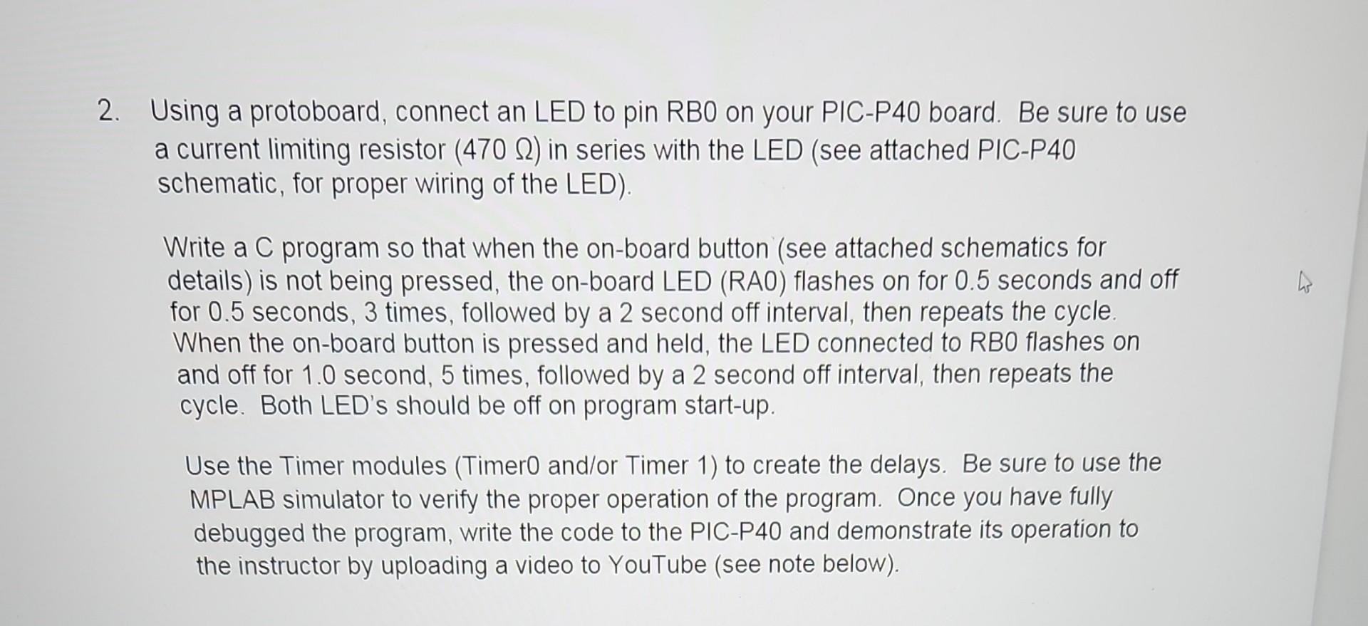
Using a protoboard, connect an LED to pin RB0 on your PIC-P40 board. Be sure to use a current limiting resistor (470) in series with the LED (see attached PIC-P40 schematic, for proper wiring of the LED). Write a C program so that when the on-board button (see attached schematics for details) is not being pressed, the on-board LED (RAO) flashes on for 0.5 seconds and off for 0.5 seconds, 3 times, followed by a 2 second off interval, then repeats the cycle. When the on-board button is pressed and held, the LED connected to RBO flashes on and off for 1.0 second, 5 times, followed by a 2 second off interval, then repeats the cycle. Both LED's should be off on program start-up. Use the Timer modules (Timer0 and/or Timer 1) to create the delays. Be sure to use the MPLAB simulator to verify the proper operation of the program. Once you have fully debugged the program, write the code to the PIC-P40 and demonstrate its operation to the instructor by uploading a video to YouTube (see note below)
Step by Step Solution
There are 3 Steps involved in it

Get step-by-step solutions from verified subject matter experts