

Question: need help in solving question 2 to 11. 1 Oxyfuel Combined Cycle This exercise deals with an oxyfuel combined cycle power plant. The idea of
need help in solving question 2 to 11.
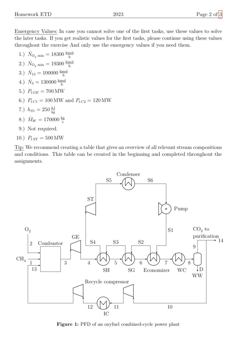
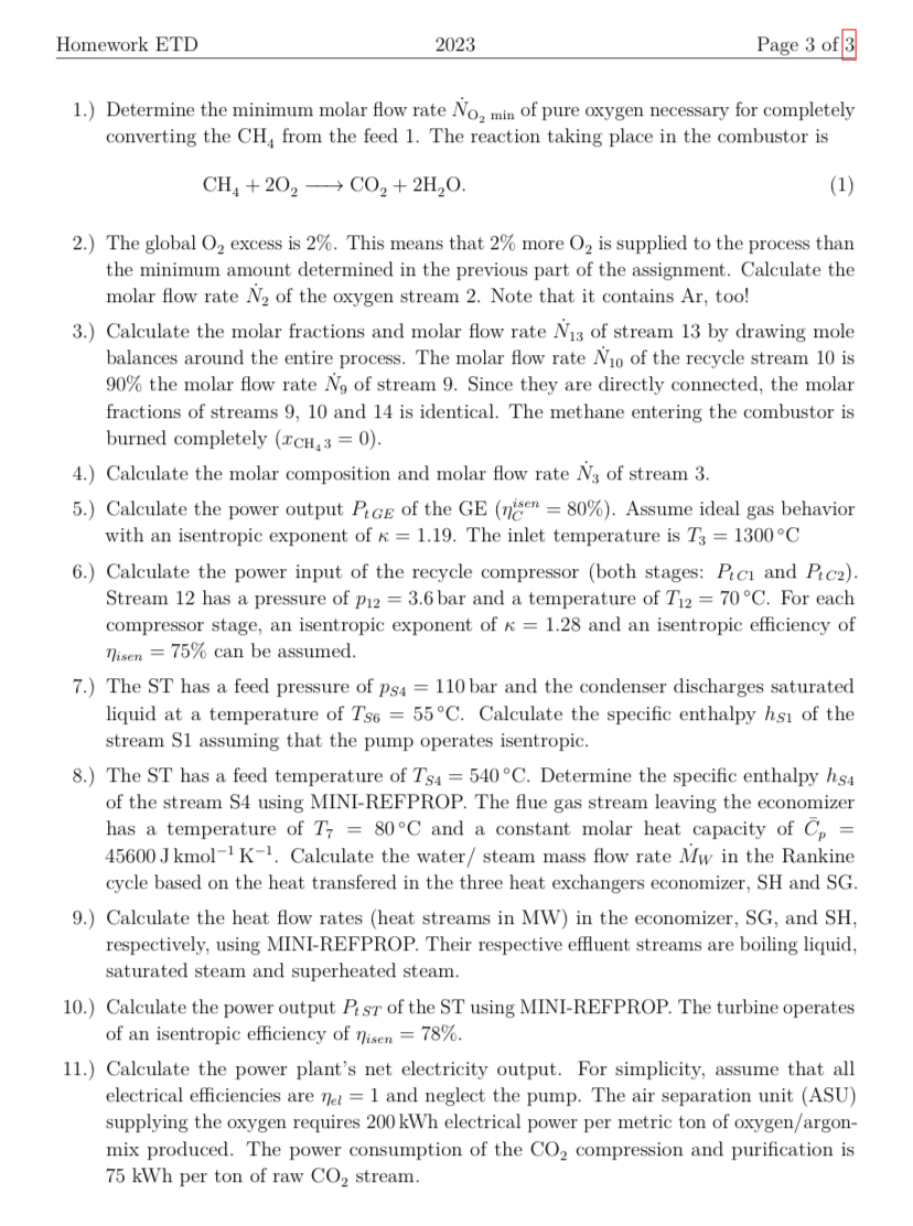
1 Oxyfuel Combined Cycle This exercise deals with an oxyfuel combined cycle power plant. The idea of a combined cycle power plant, simply put, is to utilize heat at a high temperature level in a gas turbine (GT) and then utilize the remaining low-temperature energy in a steam turbine (ST) to achieve a higher efficiency than a process using just a GT or just a ST. Oxyfuel power plants use purified oxygen instead of air as an oxidizer. As a consequence, the flue gas consists of mostly CO2 and water, which allows to relatively easily capture the CO2 downstream of the combustion. Figure 1 shows a simplified process flow diagram (PFD) of such an oxyfuel power plant. The plant is assumed to operate on MCH41=140000kgh1 of 100% pure methane (CH4) as the fuel (stream 1). As oxidizer, a stream of xO22=95.7% oxygen (O2) with xAr2=4.3% argon (Ar) is used (separating oxygen and argon is expensive and therefore avoided where possible). The combustor operates at the GT inlet pressure of p3=10 bar. The hot gas (stream 3) is expanded in the gas expander (GE) section of GT. Subsequently to the expansion, the remaining energy in the gas stream is recovered in a superheater (SH) followed by the steam generator (SG) and the economizer. Some of the water (H2O) produced in the combustion reaction is condensed out in a water cooler and separated in a drum D at p9=1.2 bar, creating a waste water stream WW that is discharged from the process. It contains only water. The gas stream (stream 9) from the drum contains mostly carbon dioxide (CO2) along with residual water (xH2O9=6%), some Ar and unconverted O2. Its temperature is T9=40C. A part of this stream is sent to a CO2 compression and purification unit (stream 14), while another part (stream 10) is recycled to the combustor. This recycle is necessary, because the temperature resulting from direct combustion of CH4 in pure O2 results in a flame temperature that is too high. A two-stage recycle compressor with an intercooler (IC) is used to compress the recycle stream. General assumptions: - All equipment except for turbines, expanders, compressors and pumps is isobaric. - The process works at steady state. - Turbines, expanders, compressors and pumps are adiabatic. - Ideal gas behavior can be assumed for the gas streams (streams that do not have an "S" in their name). - The steam table or MINI-REFPROP should be used for the water streams (those that have an "S" in their name) - Assumptions introduced in previous subtasks can be used if not noted otherwise. - Molar masses: Ar: 40kgkmol1,CH4:16kgkmol1,CO2:44kgkmol1,O2:32kgkmol1 H2O:18kgkmol1 Emergency Values: In case you cannot solve one of the first tasks, use these values to solve the later tasks. If you get realistic values for the first tasks, please continue using these values throughout the exercise And only use the emergency values if you need them. 1.) NO2min=18300hkmol 2.) NO2min=19300hkmol 3.) N13=100000hkmol 4.) N3=130000hkmol 5.) PtGE=700MW 6.) PtC1=100MW and PtC2=120MW 7.) hS1=250kgkJ 8.) MW=170000skg 9.) Not required. 10.) PtST=500MW Tip: We recommend creating a table that gives an overview of all relevant stream compositions and conditions. This table can be created in the beginning and completed throughout the assignments. Figure 1: PFD of an oxyfuel combined-cycle power plant Homework ETD 2023 Page 3 of 3 1.) Determine the minimum molar flow rate NO2min of pure oxygen necessary for completely converting the CH4 from the feed 1. The reaction taking place in the combustor is CH4+2O2CO2+2H2O 2.) The global O2 excess is 2%. This means that 2% more O2 is supplied to the process than the minimum amount determined in the previous part of the assignment. Calculate the molar flow rate N2 of the oxygen stream 2. Note that it contains Ar, too! 3.) Calculate the molar fractions and molar flow rate N13 of stream 13 by drawing mole balances around the entire process. The molar flow rate N10 of the recycle stream 10 is 90% the molar flow rate N9 of stream 9 . Since they are directly connected, the molar fractions of streams 9,10 and 14 is identical. The methane entering the combustor is burned completely (xCH43=0). 4.) Calculate the molar composition and molar flow rate N3 of stream 3 . 5.) Calculate the power output PtGE of the GE (Cisen=80%). Assume ideal gas behavior with an isentropic exponent of =1.19. The inlet temperature is T3=1300C 6.) Calculate the power input of the recycle compressor (both stages: PtC1 and PtC2 ). Stream 12 has a pressure of p12=3.6 bar and a temperature of T12=70C. For each compressor stage, an isentropic exponent of =1.28 and an isentropic efficiency of isen=75% can be assumed. 7.) The ST has a feed pressure of pS4=110bar and the condenser discharges saturated liquid at a temperature of TS6=55C. Calculate the specific enthalpy hS1 of the stream S1 assuming that the pump operates isentropic. 8.) The ST has a feed temperature of TS4=540C. Determine the specific enthalpy hS4 of the stream S4 using MINI-REFPROP. The flue gas stream leaving the economizer has a temperature of T7=80C and a constant molar heat capacity of Cp= 45600Jkmol1K1. Calculate the water/ steam mass flow rate MW in the Rankine cycle based on the heat transfered in the three heat exchangers economizer, SH and SG. 9.) Calculate the heat flow rates (heat streams in MW) in the economizer, SG, and SH, respectively, using MINI-REFPROP. Their respective effluent streams are boiling liquid, saturated steam and superheated steam. 10.) Calculate the power output PtST of the ST using MINI-REFPROP. The turbine operates of an isentropic efficiency of isen=78%. 11.) Calculate the power plant's net electricity output. For simplicity, assume that all electrical efficiencies are el=1 and neglect the pump. The air separation unit (ASU) supplying the oxygen requires 200kWh electrical power per metric ton of oxygen/argonmix produced. The power consumption of the CO2 compression and purification is 75kWh per ton of raw CO2 stream
Step by Step Solution
There are 3 Steps involved in it

Get step-by-step solutions from verified subject matter experts