

Question: Need help with the D, E, F. C.5 For these problems, we will explore a pipeline for a register-memory architecture. The architecture has two instruction
Need help with the D, E, F.
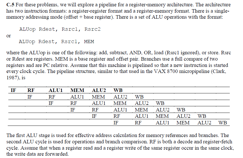
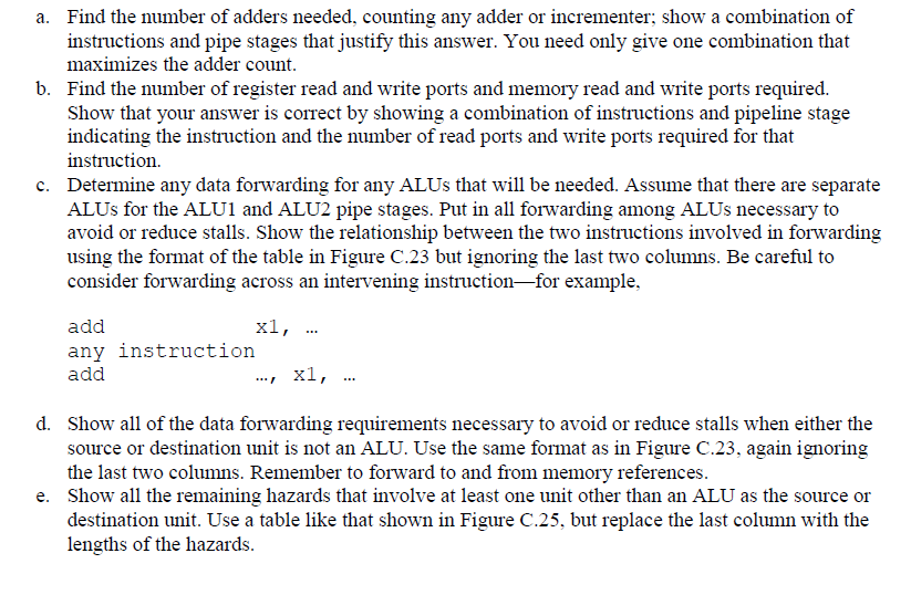
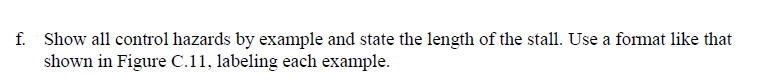
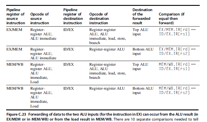
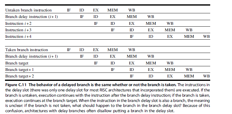
C.5 For these problems, we will explore a pipeline for a register-memory architecture. The architecture has two instruction formats: a register-register format and a register-memory format. There is a single- memory addressing mode (offset + base register). There is a set of ALU operations with the format: ALUOP Rdest, Rsrci, Rsrc2 OI ALUOP Rdest, Rsrc), MEM where the ALUop is one of the following: add, subtract, AND, OR, load (Rsrc1 ignored), or store. Rsrc or Rdest are registers. MEM is a base register and offset pair. Branches use a full compare of two registers and are PC relative. Assume that this machine is pipelined so that a new instruction is started every clock cycle. The pipeline structure, similar to that used in the VAX 8700 micropipeline (Clark, 1987), is IF RF IF ALU1 RF IF MEM ALUI RF ALU2 MEM ALUI RF IF WB ALU2 MEM ALUI RF IF IF WB ALU2 MEM ALUI RF WB ALU2 MEM ALUI WB ALU2 MEM WB ALU2 WB The first ALU stage is used for effective address calculation for memory references and branches. The second ALU cycle is used for operations and branch comparison. RF is both a decode and register-fetch cycle. Assume that when a register read and a register write of the same register occur in the same clock, the write data are forwarded. a. Find the number of adders needed, counting any adder or incrementer; show a combination of instructions and pipe stages that justify this answer. You need only give one combination that maximizes the adder count. b. Find the number of register read and write ports and memory read and write ports required. Show that your answer is correct by showing a combination of instructions and pipeline stage indicating the instruction and the number of read ports and write ports required for that instruction. c. Determine any data forwarding for any ALUs that will be needed. Assume that there are separate ALUs for the ALU1 and ALU2 pipe stages. Put in all forwarding among ALUs necessary to avoid or reduce stalls. Show the relationship between the two instructions involved in forwarding using the format of the table in Figure C.23 but ignoring the last two columns. Be careful to consider forwarding across an intervening instructionfor example, add xl, ... any instruction add x1, ... d. Show all of the data forwarding requirements necessary to avoid or reduce stalls when either the source or destination unit is not an ALU. Use the same format as in Figure C.23, again ignoring the last two columns. Remember to forward to and from memory references. e. Show all the remaining hazards that involve at least one unit other than an ALU as the source or destination unit. Use a table like that shown in Figure C.25, but replace the last column with the lengths of the hazards. f. Show all control hazards by example and state the length of the stall. Use a format like that shown in Figure C.11, labeling each example. Pipeline Pipeline Destination register of Opcode of register of Opcode of of the Comparison (if source source destination destination forwarded equal then instruction instruction instruction instruction result forward) EX/MEM Register ID/EX Register-register Top ALU EX/MEM. IR[rd] register ALU, ALU, ALU input ID/EX.IR[rsi] ALU immediate immediate, load, store, branch EX/ MEM Register- ID/EX Register-register ALU Bottom ALU EX/MEM. IR[rd] register ALU, input ID/EX.IR[r32] ALU immediate MEM/WB Register ID/EX Register-register MEM/WB.IR[rd] register ALU, ALU, ALU input ID/EX.IR[rsl] ALU immediate, load, store, immediate, branch Load MEM/WB Register ID/EX Register-register ALU Bottom ALU MEM/WB.IR[rd] register ALU, input ID/EX.IR[r32] ALU immediate, Load Figure C.23 Forwarding of data to the two ALU inputs (for the instruction in EX) can occur from the ALU result in EX/MEM or in MEM/WB) or from the load result in MEM/WB. There are 10 separate comparisons needed to tell Top ALU 1 ID EX MEM WB MEM IF ID EX WB Untaken branch instruction Branch delay instruction (i+1) Instruction i +2 Instruction i +3 Instruction i +4 IF ID EX MEM WB IF ID EX MEM WB IF ID EX MEM WB IF ID EX WB IF ID IF EX IF ID WB Taken branch instruction IF ID EX MEM WB Branch delay instruction (i+1) MEM Branch target EX MEM WB Branch target+1 ID MEM WB Branch target+2 EX MEM Figure C.11 The behavior of a delayed branch is the same whether or not the branch is taken. The instructions in the delay slot (there was only one delay slot for most RISC architectures that incorporated them) are executed. If the branch is untaken, execution continues with the instruction after the branch delay instruction; if the branch is taken, execution continues at the branch target. When the instruction in the branch delay slot is also a branch, the meaning is unclear. if the branch is not taken, what should happen to the branch in the branch delay slot? Because of this confusion, architectures with delay branches often disallow putting a branch in the delay slot
Step by Step Solution
There are 3 Steps involved in it

Get step-by-step solutions from verified subject matter experts