

Question: Note: Answer 10.4 In this problem please. Subject : Chemical Engineering ---------- -------------- 10.1 Consider the two tanks in series shown in Figure P10.1 that
Note: Answer 10.4 In this problem please.
Subject : Chemical Engineering
----------
--------------
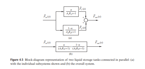
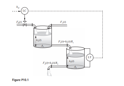
10.1 Consider the two tanks in series shown in Figure P10.1 that have been studied in Chapter 4. A control system has been installed where a level sensor/transmitter (LT) measures and transmits the liquid level in the second tank and the controller manipulates the volumetric flowrate of a stream fed to the first tank (F0(t)). A second stream is also fed to the first tank and varies uncontrollably (Fw(t)). Given a controller transfer function Gc(s), derive the transfer functions of all other hardware elements and sketch the block diagram of the feedback control system. 10.2 Repeat Problem 10.1 for the case of two tanks in series with interaction (see Figure 4.5). 10.3 Repeat Problem 10.1 for the case where the outflow of the second tank is determined by a pump (see Figure P4.6). 10.4 Repeat Problem 10.1 for the case of three tanks in series where the sensor measures the liquid level in the third tank and the controller manipulates the incoming flowrate into the first tank. ++= Figure 4.5 Block-diagram representation of two liquid storage tanks connected in parallel: (a) with the individual subsystems shown and (b) the overall system. 10.1 Consider the two tanks in series shown in Figure P10.1 that have been studied in Chapter 4. A control system has been installed where a level sensor/transmitter (LT) measures and transmits the liquid level in the second tank and the controller manipulates the volumetric flowrate of a stream fed to the first tank (F0(t)). A second stream is also fed to the first tank and varies uncontrollably (Fw(t)). Given a controller transfer function Gc(s), derive the transfer functions of all other hardware elements and sketch the block diagram of the feedback control system. 10.2 Repeat Problem 10.1 for the case of two tanks in series with interaction (see Figure 4.5). 10.3 Repeat Problem 10.1 for the case where the outflow of the second tank is determined by a pump (see Figure P4.6). 10.4 Repeat Problem 10.1 for the case of three tanks in series where the sensor measures the liquid level in the third tank and the controller manipulates the incoming flowrate into the first tank. ++= Figure 4.5 Block-diagram representation of two liquid storage tanks connected in parallel: (a) with the individual subsystems shown and (b) the overall system
Step by Step Solution
There are 3 Steps involved in it

Get step-by-step solutions from verified subject matter experts