

Question: Note: For both problems, consider that parameters x , Y , Z correspond to the last 3 digits of your student ID number, respectively. For
Note: For both problems, consider that parameters correspond to the last digits of
your student ID number, respectively. For example, if your Student ID number is :
and
Problem :
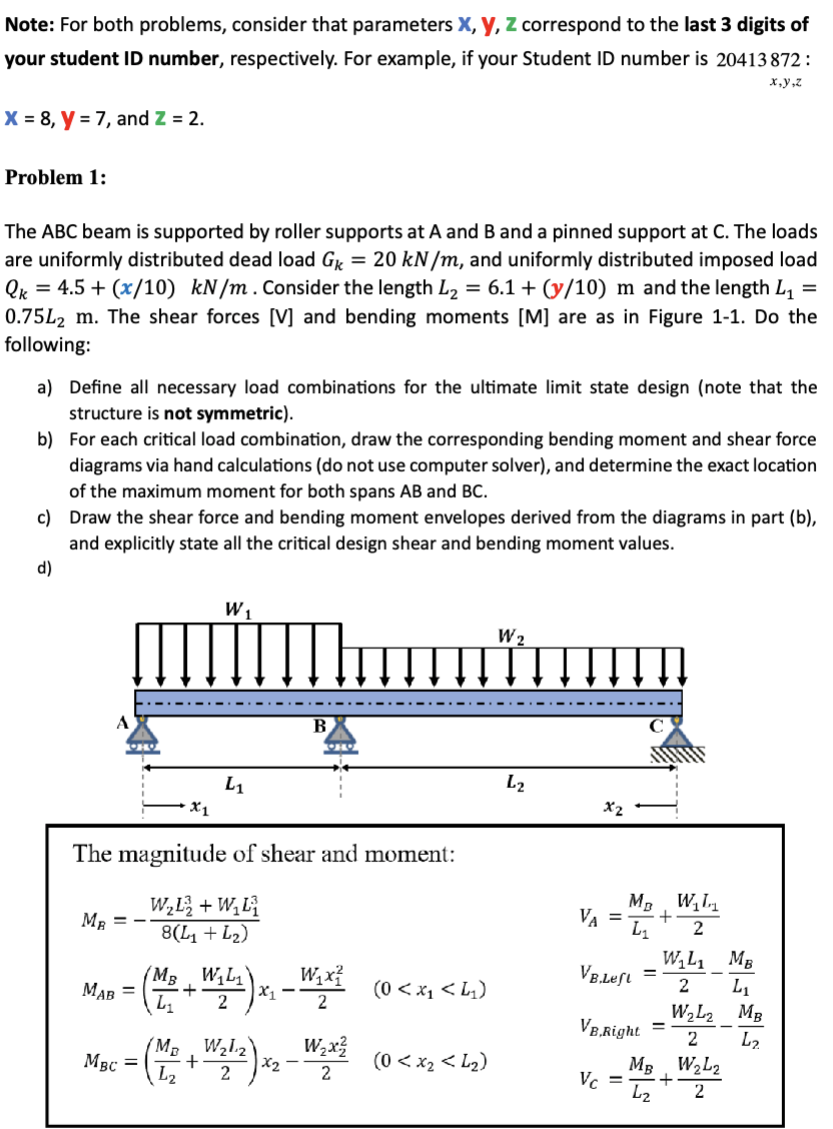
The ABC beam is supported by roller supports at A and and a pinned support at The loads
are uniformly distributed dead load and uniformly distributed imposed load
Consider the length and the length
The shear forces V and bending moments are as in Figure Do the
following:
a Define all necessary load combinations for the ultimate limit state design note that the
structure is not symmetric
b For each critical load combination, draw the corresponding bending moment and shear force
diagrams via hand calculations do not use computer solver and determine the exact location
of the maximum moment for both spans and
c Draw the shear force and bending moment envelopes derived from the diagrams in part b
and explicitly state all the critical design shear and bending moment values.
d
The magnitude of shear and moment:
Step by Step Solution
There are 3 Steps involved in it
1 Expert Approved Answer
Step: 1 Unlock

Question Has Been Solved by an Expert!
Get step-by-step solutions from verified subject matter experts
Step: 2 Unlock
Step: 3 Unlock