

Question: Note: Marks will be deducted for late submission ( 1 0 marks / day of delay ) . Your consulting engineering firm has been approached
Note: Marks will be deducted for late submission marksday of delay
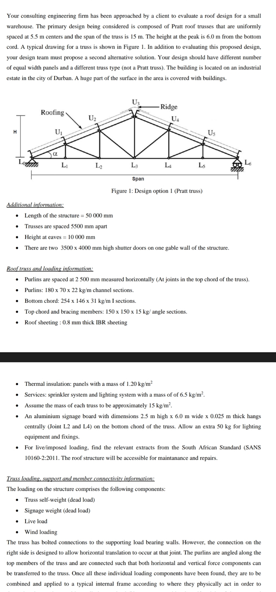
Your consulting engineering firm has been approached by a client to evaluate a roof design for a small warehouse. The primary design being considered is composed of Pratt roof trusses that are uniformly spaced at centers and the span of the truss is The height at the peak is from the bottom cord. A typical drawing for a truss is shown in Figure In addition to evaluating this proposed design, your design team must propose a second alternative solution. Your design should have different number of equal width panels and a different truss type not a Pratt truss The building is located on an industrial estate in the city of Durban. A huge part of the surface in the area is covered with buildings.
Additional information:
Length of the structure
Trusses are spaced apart
Height at eaves
There are two high shutter doors on one gable wall of the structure.
Roof truss and loading information:
Purlins are spaced at measured horizontally At joints in the top chord of the truss
Purlins: channel sections.
Bottom chord: x I sections.
Top chord and bracing members: angle sections.
Roof sheeting : thick IBR sheeting
Thermal insulation: panels with a mass of
Services: sprinkler system and lighting system with a mass of of
Assume the mass of each truss to be approximately
An aluminium signage board with dimensions high wide thick hangs centrally Joint L and L on the bottom chord of the truss. Allow an extra for lighting equipment and fixings.
For liveimposed loading, find the relevant extracts from the South African Standard SANS : The roof structure will be accessible for maintanance and repairs.
Truss loading, support and member connectivity information:
The loading on the structure comprises the following components:
Truss selfweight dead load
Signage weight dead load
Live load
Wind loading
The truss has bolted connections to the supporting load bearing walls. However, the connection on the right side is designed to allow horizontal translation to occur at that joint. The purlins are angled along the top members of the truss and are connected such that both horizontal and vertical force components can be transferred to the truss. Once all these individual loading components have been found, they are to be combined and applied to a typical internal frame according to where they physically act in order to
determine the maximum ultimate limit state load. Please note, consider the selfweight of the truss, and any live loading to act as a uniformly distributed load along the truss span which will be 'idealised' as equivalent point loads acting at the truss joints, when carrying out your analysis.
Design tasks:
a For the truss in Figure above, discuss its determinancy and stability, both internal and external. Show relevant calculations and explain your reasoning.
b Determine the design loading on a typical internal purlin and draw the bending moment diagram to obtain the maximum design moment.
c Determine the loads on a typical interior truss for the dead loads, liveloads and windloads. Show three separate diagrams of the roof truss indicating the loads on each joint as a result of the each of the above loads. Keep the four different types of loads separate. For wind loading consider all wind directions and present the case that results in the maximum possible wind loading on the structure on the main body. All other calculations ahould be included in the Appendices.
d Identify the distinct factored load combinations applicable to this system. Refer to the relevant SANS codes of practice. Compute the factored loads for each load case for the Ultimate and serviceability limit states.
e Which of the load cases do you think will result in the maximum possible loads in the truss memebers? Explain your reasoning and choice.
f Analyse a typical internal truss based on ULS vertical dead and live loading ad internal forces acting in every truss member. Use the method of joints to obtain the memb forces. Take advanatge of sym
Step by Step Solution
There are 3 Steps involved in it
1 Expert Approved Answer
Step: 1 Unlock

Question Has Been Solved by an Expert!
Get step-by-step solutions from verified subject matter experts
Step: 2 Unlock
Step: 3 Unlock